background image

DeviceNet

9

Technical data

9-3

L

BA2175 EN 2.0

9.5.1

Communication times

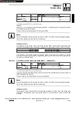
Note!

The CAN bus communication times depend on the following:

Processing time in the controller

Baud rate

Data priority

Bus load

More information about bus access control can be obtained from corresponding literature
specialised on Controller Area Networks.

9.5.1.1

Processing times in the controller

Processing times for 820X controllers

The processing times for 8200 controllers differ from the times for the 821X/822X/8200 vector series.

In opposite to the 821X/822X/824X series, which have parallel process data processing, the 8200
series process process and parameter data sequentially. Therefore the time needed to respond
process data depends on previous actions.

The processing time needed for telegrams also depends on the actual value conditioning (process
data from controller). If these data (status word, actual frequency) are not required, they can be
deactivated with the control word ” Bit 15” (PE inhibit).

Phone: 800.894.0412 - Fax: 888.723.4773 - Web: www.actechdrives.com - Email: [email protected]

Show/Hide Bookmarks

Summary of Contents for 2175

Page 1: ...Operating Instructions EDB2175EN 00423117 Fieldbus module type 2175 DeviceNet CANopen Phone 800 894 0412 Fax 888 723 4773 Web www actechdrives com Email info actechdrives com Show Hide Bookmarks ...

Page 2: ...onding Instructions for 82XX 82XX 8200 vector 93XX and 9300 Servo PLC controllers C What is new what has been changed Material no Edition Important Contents 423117 2 0 07 01 TD02 1st edition E 2001 Lenze GmbH Co KG No part of this documentation may be copied or made available to third parties without the explicit written approval of Lenze GmbH Co KG Allinformationgiveninthisonlinedocumentationhasb...

Page 3: ...sed 1 1 1 1 2 Conventions used 1 1 1 2 Items supplied 1 1 1 2 1 Legal regulations 1 2 2 Safety information 2 1 2 1 Persons responsible for safety 2 1 2 2 General safety information 2 1 2 3 Layout of the safety information 2 2 Phone 800 894 0412 Fax 888 723 4773 Web www actechdrives com Email info actechdrives com Show Hide Bookmarks ...

Page 4: ...nstallation 4 2 4 3 Electrical installation 4 3 4 3 1 Assignment of the plug socket connector 4 3 4 3 2 Voltage supply 4 4 4 3 3 Wiring to a host 4 4 4 4 Structure of a CAN bus system Example 4 5 4 4 1 CAN bus wiring 4 6 5 Commissioning 5 1 5 1 Communication profile setting 5 1 5 2 Controller address setting 5 2 5 3 Baud rate setting 5 3 5 4 Initial switch on 5 4 5 5 Drive enable via 2175 fieldbus...

Page 5: ...1 5 1006hex Communication cycle period 6 31 6 4 1 6 1008hex Manufacturer s device name 6 31 6 4 1 7 100Ahex Manufacturer s software version 6 32 6 4 1 8 100Chex Guard time 6 32 6 4 1 9 100Dhex Life time factor 6 32 6 4 1 10 1010hex Store parameters 6 32 6 4 1 11 1011hex Restore default parameters 6 33 6 4 1 12 1014hex COB ID emergency object 6 35 6 4 1 13 1015hex Inhibit time emergency 6 35 6 4 1 ...

Page 6: ...ay of current DIP switch position 6 53 6 5 2 13 L C1867 L C2367 Sync Rx identifier 6 53 6 5 2 14 L C1868 L C2368 Sync Tx identifier 6 53 6 5 2 15 L C1873 L C2373 Sync rate CAN IN1 CAN IN3 6 53 6 5 2 16 L C1874 L C2374 Sync rate CAN OUT1 CAN OUT3 6 54 6 5 2 17 L C1875 L C2375 Tx mode CAN OUT1 CAN OUT3 6 55 6 5 2 18 L C1876 L C2376 CAN OUT1 masks 6 56 6 5 2 19 L C1877 L C2377 CAN OUT2 masks 6 56 6 5...

Page 7: ...f the thick cable according to DeviceNet Specification 10 6 10 5 Features of the thin cable according to DeviceNet Specification 10 7 11 Commissioning 11 1 11 1 Communication profile setting 11 1 11 2 Controller address setting 11 2 11 3 Baud rate setting 11 2 11 4 Initial switch on 11 3 11 5 Drive enable via 2175 fieldbus module 11 4 11 5 1 Protection against uncontrolled restart 11 4 12 Paramete...

Page 8: ...tatus 14 14 14 1 5 Communication between PC and PLC 14 15 14 1 6 Starting of the RSLogix 500 English PLC program 14 17 14 2 Control program programming 14 19 14 2 1 Hardware addressing 14 19 14 2 2 Explicit messages 14 20 14 3 Program components 14 21 14 3 1 LAD 2 Main 14 22 14 3 2 LAD 3 DNET_MAIN 14 23 14 3 3 LAD30 LENZE_MAIN 14 24 14 3 4 LAD31 LENZE_PIO 14 24 14 3 5 LAD32 LENZE_EXP 14 25 14 3 6 ...

Page 9: ...Nopen L Cxxxx Lenze code Cxxxx y Subcode y of code Cxxxx e g C0410 3 subcode 3 of code C0410 Xk y Terminal strip Xk terminal y e g X3 28 terminal 28 on terminal strip X3 xx yyy Cross reference chapter page 1 1 2 Conventions used The following conventions are used to differentiate between different types of information Type of information Printing Example Names of dialog boxes input fields or selec...

Page 10: ...e fieldbus module Any other use shall be deemed inappropriate Liability The information data and notes in these Instructions met the state of the art at the time of printing Claims referring to drive systems which have already been supplied cannot be derived from information illustrations and descriptions given in these Operating Instructions The specifications processes and circuitry described in...

Page 11: ...uestions and problems please contact your Lenze representative At the time of delivery the fieldbus module meets the state of the art and ensures basically safe operation The indications given in these Operating Instructions refer to the stated hardware and software versions of the fieldbus modules The fieldbus module is hazardous if unqualified personnel works on and with the fieldbus module the ...

Page 12: ...sregarded Death or severe injuries Warning of a general danger Warning Warns of potential very hazardous situations Possible consequences if disregarded Death or severe injuries Caution Warns of potential hazardous situations Possible consequences if disregarded Light or minor injuries Warning of damage to material Stop Warns of potential damage to material Possible consequences if disregarded Dam...

Page 13: ...ol has been developed by the CiA CON in Automation in conformity with the CAL CON Application Layer All mandatory parts of the CiA DS301 protocol version 4 01 have been implemented in the 2175 bus module 3 2 Features Attachable module for the following Lenze controller series 82XX 8200 vector 93XX 9300 servo PLC The front DIP switch enables easy setting of Communication profile DeviceNet or CANope...

Page 14: ...medium ISO 11898 Rated insulation voltage Type of insulation PE 50VAC Electrical isolation External supply term 39 59 No electrical isolation Power stage 820X 821X 270 V AC Basic insulation 822X 8200 vector 270 V AC Double insulation Ins lation oltages for 93XX 270 V AC Double insulation Insulation voltages for bus systems Control terminals bus systems 820X 8200 vector with internal supply No elec...

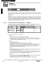
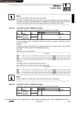
Page 15: ...e conditioning process data from controller If these data status word actual frequency are not required they can be deactivated with the control word Bit 15 PE inhibit The individual telegram times are Telegram Processing time PE inhibit 0 PE inhibit 1 Parameters 62 140 ms 62 70 ms Change of a process data value to controller 27 105 ms 27 35 ms Change of both process data values to controller 62 1...

Page 16: ...250 0 22 0 29 0 52 500 0 11 0 15 0 26 1000 0 05 0 07 0 13 Tab 3 1 Maximum telegram time in ms The telegram times indicated in the table above are calculated according to the following equation This equation allows to calculate any intermediate value tTmax if necessary tT 54 4 9 6 LD dÜ tT telegram time ms LD telegram length byte dÜ baud rate kbit s Phone 800 894 0412 Fax 888 723 4773 Web www actec...

Page 17: ...connection status l LED OFF No communication with the fieldbus module Fieldbus module is not supplied with voltage 2 two colour LED GREE N BLINKING Communication via the fieldbus has been set up RED ON Internal fault of the fieldbus module 3 Green and red drive LEDs drive Operating status of the following controllers 82XX 8200 vector 93XX and servo PLC 9300 see Operating Instructions for the contr...

Page 18: ...echanical installation Plug the fieldbus module onto the controller here 8200 vector 2175DeN020 Tighten the fixing screw 4 1 Pos 4 2175DeN021 Phone 800 894 0412 Fax 888 723 4773 Web www actechdrives com Email info actechdrives com Show Hide Bookmarks ...

Page 19: ...s through a 5 pole plug socket connector 5 4 3 2 1 2175 120R Terminal Designation Explanation 1 V GND reference for external voltage supply 2 CAN_L Data cable input for terminating resistance of 120 Ohm 3 SHIELD Shield 4 CAN_H Data cable input for terminating resistance of 120 Ohm 5 V External voltage supply see notes in chapter 10 3 3 2175DeN007 Vcc Vcc V CAN Shield CAN V 7 6 2 8 5 3 1 4 DC DC Fi...

Page 20: ...a 82EV 1x 1x Controllers with an extended AIF interface front of the 8200 vector can be internally supplied The part of the drawing highlighted in grey shows the jumper position With Lenze setting the fieldbus module is not internally supplied For internal voltage supply put the jumper in the position indicated below Lenze setting only external voltage supply Internal voltage supply 4 3 3 Wiring t...

Page 21: ...r codes or corresponding CANopen objects detailed description in chapter CANopen parameter setting 2 masters can be connected to the controllers because of the 2 parameter channels Thus parameters can be changed directly at the controller during operation of a machine or system networked via PLC using a PC e g with the user software Global Drive Control or a keypad The second parameter data channe...

Page 22: ...p to 300 m Cable type LIYCY 2 x 2 x 0 5 mm2 twisted in pairs with shield Cable resistance 40 Ω km Capacitance per unit length 130 nF km Total length up to 1000 m Cable type CYPIMF 2 x 2 x 0 5 mm2 twisted in pairs with shield Cable resistance 40 Ω km Capacitance per unit length 60 nF km Phone 800 894 0412 Fax 888 723 4773 Web www actechdrives com Email info actechdrives com Show Hide Bookmarks ...

Page 23: ...d rate L C1851 2351 6 47 The DIP switch on the front of the 2175 fieldbus module can be used for the following settings Controller address S1 S6 Baud rate S7 S9 Communication profile S10 Tip In default setting all switches are OFF The controller address and baud rate set using DIP switches will only be active after a restart Only the combinations shown in the following tables are defined 5 1 Commu...

Page 24: ... on the positions of switches S1 S6 0 OFF and 1 ON The numbers must be entered into the equation above The equation also indicates the valency of a switch The sum of valencies results in the controller address to be set Switch valencies Switch S1 S2 S3 S4 S5 S6 Valency 32 16 8 4 2 1 Example Switch S1 S2 S3 S4 S5 S6 Switch position ON ON ON OFF OFF OFF Address 56 32 16 8 0 0 0 Phone 800 894 0412 Fa...

Page 25: ...he same for all controllers and the host 1 2 3 4 5 6 7 8 910 OPEN ON OFF Baud rate kbit s S7 S8 S9 10 ON ON OFF 20 ON OFF ON 50 OFF ON ON 125 OFF ON OFF 250 OFF OFF ON 500 OFF OFF OFF 1000 ON OFF OFF Phone 800 894 0412 Fax 888 723 4773 Web www actechdrives com Email info actechdrives com Show Hide Bookmarks ...

Page 26: ...3 must come on or blink If this is not the case see chapter Troubleshooting 7 1 The green LED Controller connection status must be on too 4 1 pos 1 If this is not the case see chapter Troubleshooting 7 1 2 It should now be possible to communicate with the drive All parameters can be read and written All SDO parameters except process data such as frequency setpoint or control word can be overwritte...

Page 27: ...ex results from 5FFFhex L C0005 hex see chapter 6 2 6 5 Subindex 0 Value 10130000dec results from L C0005 1013 x 10000 2 Set the parameter L C0142 to 0 Please see chapter Protection against uncontrolled restart 3 Terminal 28 RFR controller enable is always active and must be set to HIGH during CANopen operation see the Operating Instructions for 93XX The controller can also be enabled via CANopen ...

Page 28: ...CANopen 5 Commissioning 5 6 L BA2175 EN 2 0 Phone 800 894 0412 Fax 888 723 4773 Web www actechdrives com Email info actechdrives com Show Hide Bookmarks ...

Page 29: ...stored in the controller take L C0003 into account Process data PDO Process Data Objects These are for instance Setpoints Actual values Exchange between host and controller required as fast as possible Small amounts of data which can be transferred cyclically Process data channel chapter 6 3 The controller can be controlled using process data The host has direct access to process data In the PLC t...

Page 30: ...detail For more information please see the homepage of CAN in Automation CiA www can cia de 6 1 1 Identifiers The CAN bus system is message oriented One of the most important components of a data telegram is the identifier Except for the network management see chapter 6 1 2 and the sync telegram see chapter 6 3 the identier contains the controller address Identifier basic identifier controller add...

Page 31: ...o restart the entire initialisation phase or parts of it by transferring different telegrams All parameters already set are overwritten with their standard values After initialisation 2 has been completed the participant is automatically set to the status Pre operational From that moment on the master determines the controller communication The master changes a status for the whole network A targe...

Page 32: ... a request from the master If the master does not send a request a life guarding event will be initialised If the slave does not send a response to a request from the master a node guarding event will be initialised Tip The response to a life guarding event is set under code L C1882 L C2382 NMT master NMT slave s 4 STOPPED s 5 OPERATIONAL s 127 PREOPERATIONAL Phone 800 894 0412 Fax 888 723 4773 We...

Page 33: ...rk In Lenze controllers parameters to be changed are listed as codes Controller codes are addressed via the index when accessing the code through a 2175 fieldbus module see chapter 6 2 1 The index for Lenze code numbers is between 16576 40C0hex and 24575 5FFFhex Conversion formula Index dec 24575 Lenze code number Example Lenze codes dec hex Addressing of Lenze codes via offset Index 24575 LENZE C...

Page 34: ...structions or the Manual for 93XX Changes of the current parameter set will be lost after If a parameter is available only once see Operating Instructions for 82XX or 8200 vector use code digit offset 0 current parameter set will be lost after switching off the controller Code C0003 is for saving the current parameter set After s itching on the controller Example for L C0011 maximum field frequenc...

Page 35: ...ontroller response to write request acknowledgement 60 60 60 Writing not possible Read Request Request to read a parameter from the drive 40 40 40 40 Read Response Response to the read request with an actual value 43 4B 4F 41 Error response Controller indicates communication error 80 80 80 80 Details about the 2nd byte 3rd byte Details about the parameter data telegram Index Low byte Index High by...

Page 36: ...g on the data format see Attribute list in the Manual the parameter value needs 1 to 4 bytes Tip Lenze parameters are mainly FIX32 data 32 bit value with signal decimal with four decimal codes see the Attribute Table in the corresponding Manual Integers are the result of a multiplication of a parameter value by 10000 Parameters C0135 and C0150 must be transferred as bit code and without factor Err...

Page 37: ...bjects to be transferred longer than PDO 0604 0043 General parameter incompatibility 0604 0047 General internal controller incompatibility 0606 0000 Access denied because of hardware error 0607 0010 Inappropriate data type service parameter length 0607 0012 Inapproriate data type service parameter length exceeded 0607 0013 Inapproriate data type service parameters not long enough 0609 0011 Subinde...

Page 38: ...000 ú 0 24514 5FC2hex Telegram to drive Identifier Command Index Low Byte Index High Byte Subindex Data 1 Data 2 Data 3 Data4 1541 40hex C2hex 5Fhex 00 00 00 00 00 Telegram from drive Identifier Parameter channel 1 of controller 1408 controller address 1413 Command Read response to read request with the current value of 43hex Index of read request 5FC2hex Subindex 0 Data 1 to Data 4 43 C S 10 000 ...

Page 39: ...0 Calculation of the acceleration time Acceleration time value 20 s ú 10 000 200 000 00 03 0D 40hex Telegram to drive Identifier Command Index Low Byte Index High Byte Subindex Data 1 Data 2 Data 3 Data4 1537 23hex F3hex 5Fhex 00 40hex 0Dhex 03hex 00 Response of the controller when no fault occurs Identifier Command Index Low Byte Index High Byte Subindex Data 1 Data 2 Data 3 Data4 1409 60hex F3he...

Page 40: ...byte 3rd byte 4th byte 5th byte 6th byte 7th byte 8th byte 60hex 00 00 00 00 00 00 00 1st byte 60hex Write response acknowledgement with access to bytes 2 8 Note The individual blocks are toggled one after the other i e the request with command 60 hex 0110 0000bin is before command 70hex 0111 0000bin and followed by 60hex again etc The response is sent accordingly It is alternating because of a to...

Page 41: ... identically for all parameter sets 93XX controllers With 93XX controllers it is not possible to select a setpoint source which can be set using just one code On the other hand these controllers can be adapted to drive tasks without special programming knowledge since it uses preconfigured function blocks The function blocks can be combined and connected by the user himself It is however safer to ...

Page 42: ...blocks are converted into corresponding signal types The control word is especially important for the drive Byte 1 and byte 2 of the user data contain the controller setpoint Byte 1 Identifier Byte 2 Byte 3 Byte 4 Byte 5 Byte 6 Byte 7 Byte 8 Byte 3 4 Byte 5 6 Byte 7 8 X1 Control word AIF1 IN Byte 1 2 Tab 6 2 Example 93XX series Process data telegram from drive The function block to be used for cyc...

Page 43: ...ocess from the controller PDO from controller PDO to controller Sync telegram Sync telegram PDO to Controller t1 t t1 Fig 6 2 Synchronisation of cyclic PDOs seen from the bus participant s view Note for Fig 6 2 At t1 all PDOs accept process data as soon as a sync telegram is received Tip SDOs or event controlled PDOs are asynchronously accepted by controllers i e aftertransmission has been complet...

Page 44: ... which can also be written as parameter under C046 is entered here as process data word about process data Byte 4 The frequency setpoint which can also be written as parameter under C046 is entered here as process data word The normalisation differs from the setting under C046 It is a signed value 24000 480 Hz Telegram Byte 5 Telegram Byte 6 No evaluation of these data anything possible Byte 7 No ...

Page 45: ...ocess Byte 3 Actual frequency value with signed normalisation L C0050 about the process data Byte 4 Actual frequency value with signed normalisation L C0050 24000 480 Hz is provided here data telegram Byte 5 telegram Byte 6 No evaluation of these data anything possible Byte 7 No evaluation of these data anything possible Byte 8 Status word see chapter 6 3 4 2 16 bit 16 bit B15 B12 B0 B1 B2 B3 B4 B...

Page 46: ...te AIF IN W2 High byte xx xx Control word see chapter 6 3 4 1 AIF IN Wx is parameterised under code L C0412 AIF AIF IN AIF CTRL AIF IN W2 AIF IN W1 B15 B12 B0 B1 B2 B3 B4 B8 B9 B10 B11 DCTRL QSP CINH TRIP SET TRIP RESET DCTRL 16 bit 16 bit 16 bit 2141LON011 L C0410 x 10 L C0410 x 11 L C0410 x 12 L C0410 x 22 L C0410 x 25 L C0412 x 10 L C0412 x 11 Fig 6 5 Function block AIF IN in 8200 vector freely...

Page 47: ... 16 bit B15 B12 B0 B1 B2 B3 B4 B8 B9 B10 B11 16 bit B13 B14 B5 B6 B7 B0 C0417 1 AIF OUT W1 AIF OUT W2 B1 DCTRL1 IMP B2 C0417 3 B3 C0417 4 B4 C0417 5 B5 C0417 6 B6 DCTRL1 NOUT 0 B7 DCTRL1 CINH B8 DCTRL1 STAT 1 B9 DCTRL1 STAT 2 B10 B11 DCTRL1 STAT 4 DCTRL1 STAT 8 B12 DCTRL1 OH WARN B13 DCTRL1 OV B14 C0417 15 B15 C0417 16 AIF STAT1 C0421 1 C0421 2 2141LON013 Fig 6 6 Function block AIF OUT in 8200 vec...

Page 48: ...ero active NSET1 RFG1 0 0 not active 1 active Freely configurable by user 06 Reserved UP function for motor potentiometer 0 UP not active 1 UP active MPOT1 UP 0 not active 1 active Freely configurable by user 07 Reserved DOWN function for motor potentiometer 0 DOWN not active 1 DOWN active MPOT1 DOWN 0 not active 1 active 08 Reserved Reserved Freely configurable by user 09 Ctrl inhibit controller ...

Page 49: ...1 NOUT 0 7 Ctrl inhibit controller inhibit 0 controller not inhibited 1 controller inhibited Ctrl inhibit controller inhibit 0 controller not inhibited 1 controller inhibited DCTRL1 CINH 8 11 controller status 0 Controller initialization 8 Error active controller status 0 Controller initialization 1 Switch on inhibit 3 Operation inhibited 4 Flying restart circuit active 5 DC brake active 6 Operati...

Page 50: ...determines the input data of the controller as data interface for the 2175 fieldbus module For more detailed information about the AIF IN function block see the 93XX Manual Signal configuration L C0005 AIF IN W1 AIF IN W2 AIF IN W3 AIF IN D1 Speed control 1003 1013 1113 NSET N Speed setpoint 100 16383 Torque control 4003 4013 4113 MCTRL MADD Torque setpoint 100 16383 not assigned DF master 5003 50...

Page 51: ... RESET CSEL1 LOAD not assigned not assigned not assigned 8 not assigned not assigned not assigned not assigned not assigned not assigned not assigned not assigned not assigned 9 AIF CTRL CINH AIF CTRL CINH AIF CTRL CINH AIF CTRL CINH AIF CTRL CINH AIF CTRL CINH AIF CTRL CINH AIF CTRL CINH AIF CTRL CINH 10 AIF CTRL TRIP SET AIF CTRL TRIP SET AIF CTRL TRIP SET AIF CTRL TRIP SET AIF CTRL TRIP SE T AI...

Page 52: ... I I N 2 1 3 6 0 3 1 6 B i t 1 6 B i t A I I N W 2 A I I N W 3 1 6 B i n ä r s i g n a l 1 6 B i t ˇ ˆ W ˆ r 1 6 B i t i g W ˆ r 1 6 B i n ä r s i g n a l 1 6 B i t A I I N W 1 A I I N B 1 A I I N B A I I N 1 A I ˇ B 1 2 A I ˇ B 1 3 A I ˇ B 1 A I ˇ B 1 B t 3 B t 6 B t A I F I N B i t B i t 1 t r ˆ r t A I ˇ B A I ˇ B 1 A I ˇ B 2 A I ˇ B A I ˇ B A I ˇ B 6 A I ˇ B D C T R L A I ˇ B 3 I A B ˇ A I ˇ B...

Page 53: ... display 100 16383 MCTRL NSET2 Speed controller input 100 16383 Torque control 4003 4013 4113 MCTRL MSET2 Torque display 100 16383 MCTRL NACT Act speed in 100 16383 MCTRL NSET2 Speed controller input 100 16383 DF master 5003 5013 5113 MCTRL NACT Actual speed 100 16383 MCTRL MSET2 Torque display 100 16383 MCTRL NSET2 Speed controller input 100 16383 DF slave bus 6003 6013 6113 MCTRL NACT Actual spe...

Page 54: ...T CDATA X0 QMIN QMIN QMIN 6 DCTRL NACT 0 DCTRL NACT 0 DCTRL NACT 0 DCTRL NACT 0 DCTRL NACT 0 DCTRL NACT 0 DCTRL NACT 0 DCTRL NACT 0 DCTRL NACT 0 7 DCTRL CINH DCTRL CINH DCTRL CINH DCTRL CINH DCTRL CINH DCTRL CINH DCTRL CINH DCTRL CINH DCTRL CINH 8 11 Controller status 8 11 0 1 3 4 5 6 7 8 10 Unit initialisation Switch on inhibit Operation inhibited Flying restart circuit active DC injection brakin...

Page 55: ... 1 B t B t 6 X 1 B t 3 1 2 3 1 2 2 A I 1 2 1 1 6 B i t ˇ ˆ W ˆ r 1 6 B i t i g W ˆ r 1 1 6 B i t ˇ ˆ W ˆ r 1 6 B i t i g W ˆ r 1 A I 1 2 W 1 0 1 0 1 1 1 A I 1 2 W 2 0 2 A I 1 2 W 3 0 3 0 2 0 3 A B ˇ I 3 A B 1 A B 1 1 6 B i t F D O 1 1 6 0 1 1 1 6 0 1 6 1 1 6 1 3 1 1 1 6 0 1 1 1 6 0 3 2 B i t B i t 1 1 6 0 1 S T A T 1 6 0 6 1 6 0 3 3 A I 1 2 2 1 1 1 1 6 1 6 B i t ˇ ˆ W ˆ r 1 6 B i t i g W ˆ r Fig 6...

Page 56: ...string with indicated length Overview Index hex Subindex hex Name Data type Authorisation 1000 0 Device type U32 ro 1001 0 Error register U8 ro 1003 0 Recording numbers of error U8 rw 1003 1 Standard error field U32 r0 1005 0 Identifier sync message U32 rw 1006 0 Communication cycle period U32 rw 1008 0 Manufacturer device name Visible string 9 characters const 100A 0 Manufacturer software version...

Page 57: ...mm ro 1 PDO1 identifier PDO comm rw 2 Transmission type rw 1801 Transmit PDO2 parameter 1801 0 Number of supported subindexes PDO comm ro 1 PDO2 identifier PDO comm rw 2 Transmission type rw 1802 Transmit PDO3 parameter 1802 0 Number of supported subindexes PDO comm ro 1 PDO3 identifier PDO comm rw 2 Transmission type rw 1A00 Transmit PDO1 mapping parameter 1A00 0 Number of mapped objects in PDOs ...

Page 58: ... 3 Bit 2 Bit 1 Bit 0 0 0 0 0 0 0 0 0 No TRIP 1 Controller TRIP error in CANopen module For error analysis see L C0161 in corresponding Operating Instructions 6 4 1 3 1003hex Pre defined error field Error history Index hex Subindex Name Data type Authorisation 1003 0 Recording numbers of error U8 rw 1003 1 Standard error field U32 r0 This object shows that errors occurred in the module and the basi...

Page 59: ...ier 0 0 0 0 0 0 0 0 0 0 0 0 0 0 0 0 0 0 0 0 1 X Bit no Value Explanation 0 10 X Identifier see chapter 6 1 1 11 28 0 The extended identifier 29 bit is not supported for the 2175 fieldbus Any of these bits must be 0 29 0 The extended identifier 29 bit is not supported for the 2175 fieldbus Any of these bits must be 0 30 0 1 Device does not create SYNC telegrams Device creates SYNC telegrams 31 X An...

Page 60: ...fe time factor is not to be supported the default setting of 0 should not be changed For further information see chapter 6 1 2 1 6 4 1 10 1010hex Store parameters Parameter storage in the EEPROM Index hex Subindex Name Data type Authorisation 1010 0 Store parameters U32 ro rw 1010 1 3 Store parameters U32 ro rw The subindexes 1 2 and 3 are presently not supported Parameter storage Error messages o...

Page 61: ...ault parameters U32 rw ro In addition to index and subindex telgram data must include the signature load to start the parameter download see table Signature MSB LSB ISO 8859 ASCII d a o l hex 64 61 6F 6C Bit assignment for reading right U32 0 1 31 0 Download not possible 1 Download possible 0 0 0 0 0 0 Subindex Rights Write Read 0 ro The following error message occurs while writing 0601 0002hex Ma...

Page 62: ...lows 1st byte 2nd byte 3rd byte 4th byte 5th byte 6th byte 7th byte 8th byte Emergency error code LENZE Error code 10XX Error register Object 1001hex Field for manufacturer specific error messages 6 4 1 13 1015hex Inhibit time emergency This object determines the time between an internal module error and the sending of the error message via the bus COB ID emergency object code 1014hex Only integer...

Page 63: ...r specification 1201 0 1 2 Server SDO parameter Identifier client Server rx Identifier server Client tx SDO Param ro rw rw 1 Receive identifier specification 2 Send identifier specification Data telegram assignment 5th byte 6th byte 7th byte 8th byte U32 0 10 11 28 29 30 31 11 bit identifier 0 0 0 0 0 0 0 0 0 0 0 0 0 0 0 0 0 0 0 0 0 1 Explanation Bit no Value Explanation 0 10 0 1 Identifier see ch...

Page 64: ... Every bit must become 0 30 0 1 RTR to this PDO possible Lenze RTR to this PDO not possible cannot be set RTR remote transmission request 31 MSB 0 1 0 PDO active 1 PDO not active PDO transmission Acceptance as of Explanation cyclic synchronous event controlled Acceptance as of signal No n Explanation X X n 1 240 By entering value n this PDO will be accepted by every n th SYNC 6 4 1 17 1401hex Rece...

Page 65: ... 0 Number of entries PDO comm ro Subindex 0 Max supported subindex 2 Subindex 1 Identifier setting for this PDO 1402 1 COB ID used by PDO rw Subindex 1 Identifier setting for this PDO 200hex node ID 6 2 2 Transmission type rw 200hex node ID 6 2 Subindex 2 Transfer type setting see table The further description of this object is the same as in chapter 6 4 1 16 Phone 800 894 0412 Fax 888 723 4773 We...

Page 66: ...0hex 4 PDO mapping 4 by the value 10hex 6 4 1 20 1601hex Receive PDO2 mapping parameter With this object parameter data can be received as PDO2 Tip At present this functionality is not available Depending on the subindex the following values are returned when reading the object Subind 0 value 4hex Subind 1 4 value 10hex Object not available for 82XX 8200 vector and 93XX controllers Index hex Subin...

Page 67: ...alue 10hex Object not available for 82XX 8200 vector and 93XX controllers Index hex Subindex Name Data type Authorisation Explanation 1600 0 Number of mapped objects in PDOs PDO mapping Subindex 0 Max supported subindex 4 1 PDO mapping 1 ro 2 PDO mapping 2 ro Read request of this object are responded 3 PDO mapping 3 Read request of this object are responded by the value 10hex 4 PDO mapping 4 by th...

Page 68: ...x 2 1801 1 PDO identifier PDO Comm rw Identifier setting for this PDO 280hex node ID 1801 2 Transfer type PDO Comm rw Transfer type setting see table Transfer type PDO transfer Explanation Transfer type cyclic synchronous event controlled Explanation 1 240 X X With the entry of value n this PDO is sent at every n SYNC 254 X 6 4 1 24 1802hex Transmit PDO3 parameter Sending of process data Tip Objec...

Page 69: ...apping 3 PDO mapping ro 4 PDO mapping 4 6 4 1 26 1A01hex Transmit PDO2 mapping parameter With this object parameter data can be sent as PDO2 Tip At present this functionality is not available Depending on the subindex the following values are returned when reading the object Subind 0 value 4hex max supported subindex Subind 1 4 Read requests of this object are responded by 10hex Object not availab...

Page 70: ...the object Subind 0 value 4hex max supported subindex Subind 1 4 Read requests of this object are responded by 10hex Object not available for 82XX 8200 vector and 93XX controllers Index hex Subindex Name Data type Authorisation 0 Number of mapped objects in PDOs 1A02 1 PDO mapping 1 1A02 2 PDO mapping 2 PDO mapping ro 3 PDO mapping 3 PDO mapping ro 4 PDO mapping 4 Phone 800 894 0412 Fax 888 723 47...

Page 71: ...he controller is know as system device The devices are detected while the modules are initialised Address and baud rate can be set in different ways see 5 1 Front switch 1 6 OFF Address and baud rate are determined by switch position The 2175 fieldbus module writes the front switch position to codes L C1859 and L C2359 Front switch 1 6 OFF Address and baud rate must be set under codes L C0009 addr...

Page 72: ...ay L C1856 1 5 58BFh 22719d 1 3000 ms 2 5 0 ms 0 1 ms 65535 FIX32 Boot up and cycle times L C1857 1 4 58BEh 22718d 3000 ms 0 1 ms 65535 FIX32 Monitoring time L C1859 58BCh 22716d 0 1 1023 U16 DIP switch position display L C1860 58BBh 22715d 0 1 1023 U16 Current DIP switch position display L C1867 58B4h 22708d 128 0 1 2047 FIX32 Sync Rx identifier L C1868 58B3h 22707d 128 0 1 2047 FIX32 Sync Tx ide...

Page 73: ...4Xxh 18XXh FIX32 CAN INx CAN OUTx addressing L C2354 1 6 56CDh 22221d 1 129 2 1 3 257 4 258 5 385 6 386 0 1 1663 FIX32 CAN IN CAN OUT selective addressing L C2355 1 6 56CCh 22220d 0 1 2047 FIX32 Resulting identifier display L C2356 1 5 56CBh 22219d 1 3000 ms 2 5 0 ms 0 1 ms 65535 FIX32 Boot up and cycle times L C2357 1 4 56CAh 22218d 3000 ms 0 1 ms 65535 FIX32 Monitoring time L C2359 56C8h 22216d ...

Page 74: ...enze Selection Data type L C1850 58C5h 22725d 1 1 1 63 FIX32 L C2350 56D1h 22225d 1 1 1 63 FIX32 This code can be used to set the 2175 module address via the CAN bus Code L C1850 maps code L C0009 of the basic unit Writing to L C1850 has a direct effect on L C0009 Note This code is only effective if the DIP switches S1 S6 have been switched OFF before mains switching A node address modification wi...

Page 75: ... Subcode Index Lenze Selection Data type L C1852 58C3h 22723d 0 0 Slave operation FIX32 L C2352 56CFh 22223d 0 0 Slave operation 1 Master operation FIX32 After power on the module sets PRE OPERATIONAL status With this status parameter data SDOs can only be exchanged In slave operation the module remains in this status until the network management command Start_remote_node is put into OPERATIONAL s...

Page 76: ...n The addressing of the corresponding PDO pair and the subcode under code L C1853 L C2353 is changed to CANopen index 14XXh 18XXh see above value 3 if CANopen index 1400h 1401h 1402h 1800h 1801h or 1802h get new values Identifier calculation to CANopen via code L 1854 L 2354 via to CANopen index PDO to CANopen Default setting via Lenze system bus to CANopen index CAN IN1 512 node address 384 C1854...

Page 77: ...de L C1853 L C2353 selective addressing Note An address modification in one or several subcodes becomes effective when the module is switched on again or when a network management command is sent to the module via the CAN bus Reset_node and L C2120 1 or Reset_communication 6 5 2 8 L C1855 L C2355 Display of resulting identifiers Possible settings Code Subcode Index Lenze Selection Data type L C185...

Page 78: ...ng Note A sync TX cycle time change becomes effective immediately 0 in L C1856 5 and L C2356 5 deactivates cyclic sync telegram sending CANopen relation The CANopen index 1006h communication cycle period corresponds to the settings under codes L C1856 5 and L C2356 5 Zeitbasis µs Since the data processing rate of the 2175 module is 1000 µs the input via CANopen index 1006h is an integer multiple o...

Page 79: ...C2357 4 A response time can be set even if the device changes into a BUS OFF status Monitoring response see codes L C1882 and L C2382 6 5 2 11 L C1859 L C2359 Display of DIP switch position Possible settings Code Subcode Index Lenze Selection Data type L C1859 58BCh 22716d 0 1 1023 U16 L C2359 56C8h 22216d 0 1 1023 U16 Indicated is the DIP switch position when initialising the module Valency table...

Page 80: ...ode The identifier of new value written in index 1005hwill also be accepted by code L C1867 L C2367 The value saved in L C1868 L C2368 will be displayed while reading the CANopen index 6 5 2 14 L C1868 L C2368 Sync Tx identifier Code Index Possible settings Code Subcode Index Lenze Selection Data type L C1868 58B3h 22707d 128 0 1 2047 FIX32 L C2368 56BFh 22207d 128 0 1 2047 FIX32 The code contains...

Page 81: ...and L C2373 subcode 3 If for instance index 1402h is read the response value comes from code L C1873 or L C2373 subcode 3 If a new value is written to index 1401 h also code L C1873 or L C2373 subcode 2 will be overwritten with this value 6 5 2 16 L C1874 L C2374 Sync rate CAN OUT1 CAN OUT3 Code Index Possible settings Code Subcode Index Lenze Selection Data type L C1874 1 CAN OUT1 2 CAN OUT2 58AD...

Page 82: ...0 2 0 3 0 FIX32 not effective when using 82XX 8200 vector and 93XX controllers Value 0 Output PDOs are sent when a sync telegram is received Only sync telegrams with the identifier set under L C1867 L C2367 count as received telegrams L C1874 L C2374 can also be used for setting a number of sync telegrams n 1 240 after which output PDO are to be sent Value 1 Output PDOs are not sent This selection...

Page 83: ...OUT 1 process data object is set to 20 hex under code L C1876 3 see MASK Please observe the field highlighted in grey 1st cycle Result after 1st cycle PDO is sent CAN OUT 1 W3 MASK 0 0 0 0 0 0 0 0 0 0 1 0 0 0 0 0 Data 1 1 1 1 1 1 1 1 0 1 1 0 0 0 1 0 Result 0 0 0 0 0 0 0 0 0 0 1 0 0 0 0 0 2nd cycle New data is written to CAN OUT1 after the 2nd cycle Result after 2nd cycle PDO not sent because of bi...

Page 84: ...ol has been developed for monitoring the master slave connection A time in milliseconds can be entered in CANopen index 100Ch guard time Index 100Dh life time factor saves a factor The monitoring time time in which the master sends a certain telegram to the slave 2175 IB results from multiplying the two indexes If one of the indexes is set to zero the monitoring time is zero too and thus deactivat...

Page 85: ...can be monitored from the 9300 servo PLC by reading the status byte The user can take measures against this process AIF status byte Description Bit 0 CE11 error CAN IN1 monitoring time exceeded Bit 1 CE12 error CAN IN2 monitoring time exceeded Bit 2 CE13 error CAN IN3 monitoring time exceeded Bit 3 CE14 error module in BUS OFF status Bit 4 Operational status Bit 5 Preoperational status Bit 6 Warni...

Page 86: ...will be ignored After parameter setting the controller needs up to approx 70 ms to set the status enabled terminal C040 C0135 The TRIP reset function is activated by inhibiting the controller and enabling it again under C040 or C0135 The TRIP reset function initializes the 8200 inverter and the 2175 fieldbus module Therefore the TRIP reset command is not acknowledged for the master 6 6 2 8200 vect...

Page 87: ...he controller to the 2175 fieldbus module The control byte can be accessed via code C2120 The commands are defined as numbers Some of the command numbers apply to all fieldbus modules others only apply to certain modules Altogether up to 16 commands can be used Order number in C2120 bit0 3 Function R W code 0 No command 1 New initialisation of optional module all 2 Update of all relevant codes for...

Page 88: ...CANopen 6 Parameter setting 6 60 L BA2175 EN 2 0 Phone 800 894 0412 Fax 888 723 4773 Web www actechdrives com Email info actechdrives com Show Hide Bookmarks ...

Page 89: ... the controller yet Possibility 1 Controller not switched on see fault possibility 1 Possibility 2 Check the connection to the controller Does the controller receive telegrams The LED Bus connection status on the fieldbus 4 1 must be blinking in green h th d i i i ti ith Check whether the connection corresponds to the instructions given in chapter CAN bus wiring page 4 1 Check whether host sends t...

Page 90: ...CANopen 7 Troubleshooting and fault elimination 7 2 L BA2175 EN 2 0 Phone 800 894 0412 Fax 888 723 4773 Web www actechdrives com Email info actechdrives com Show Hide Bookmarks ...

Page 91: ... Access via the fieldbus module 6 5 Code numbers index Conversion 6 5 Codes Lenze 6 5 Commissioning 5 1 Communication medium 3 2 Communication profile 5 1 Communication profile setting 5 1 Communication times 3 3 Connection Connections of the fieldbus module 4 3 Plug in terminal 5 pole 4 3 Control word 6 13 8200 vector 6 20 82XX 6 20 93XX 6 23 6 26 Controller Application as directed 1 2 Labelling ...

Page 92: ...et connector Assignment 4 3 Process data channel 4 5 Process data telegram from controller 6 17 to controller 6 16 Process data transfer 6 14 Processing times 8210 3 3 8200 3 3 in the controller 3 3 R Rated data 3 2 S Safety information 2 1 Layout 2 2 Other notes 2 2 Warning of damage to material 2 2 Warning of damage to persons 2 2 Operating Instructions 1 1 Setpoint source 6 13 T Technical data ...

Page 93: ...ically actuated pneumatic valves frequency inverters and servos The units are directly connected to the network This means reduced costs for installation commissioning maintenance tests and upgrading of the system The 2175 fieldbus module with the communication profile DeviceNet is a ONLY SERVER module of group 2 9 2 Features Attachable module for the following Lenze controller series 820X 821X 82...

Page 94: ...Type of insulation PE 50VAC Electrical isolation External supply term 39 59 No electrical isolation Power stage 820X 821X 270 V AC Basic insulation 822X 8200 vector 270 V AC Double insulation Ins lation oltages for 93XX 270 V AC Double insulation Insulation voltages for bus systems Control terminals bus systems 820X 8200 vector with internal supply No electrical isolation 8200 vector with external...

Page 95: ...ontrollersdiffer from the timesfor the821X 822X 8200 vectorseries In opposite to the 821X 822X 824X series which have parallel process data processing the 8200 series process process and parameter data sequentially Therefore the time needed to respond process data depends on previous actions The processing time needed for telegrams also depends on the actual value conditioning process data from co...

Page 96: ...possible The processing times for process data refer to the sync telegram chapter 6 3 6 13 Processing times for 821X 8200 vector 822X controllers Parameters 30 50 ms Process data 3 5 ms Processing time for 93XX Parameter data and process data are independent of each other Parameter data approx 30 ms 20 ms tolerance typically Some codes require longer processing times see the 9300 Manual Process da...

Page 97: ...llows to calculate any intermediate value tTmax if necessary tT 54 4 9 6 LD dÜ tT telegram time ms LD telegram length byte dÜ baud rate kbit s 9 5 1 3 Maximum bus length Depending on the baud rate and the cable used the following bus lengths are possible Baud rate Kbit s Thin cable Thick cable 125 500 m 250 100 m 250 m 500 100 m When using both thick and thin cable types see 10 6 and 10 7 the maxi...

Page 98: ...DeviceNet 9 Technical data 9 6 L BA2175 EN 2 0 Phone 800 894 0412 Fax 888 723 4773 Web www actechdrives com Email info actechdrives com Show Hide Bookmarks ...

Page 99: ... supplied with voltage 2 Connection status GREE N BLINKING Dup_Mac_ID testing Still no connection to the master 2 Connection status two colour LED GREE N ON DeviceNet connection built up RED BLINKING No communication because time limit exceeded RED ON Internal fault of the fieldbus module 3 Green and red drive LEDs drive Operating status of the following controllers 82XX 8200 vector 93XX and servo...

Page 100: ...EN 2 0 10 2 Mechanical installation Plug the fieldbus module onto the controller here 8200 vector Tighten the fixing screw 10 1 Pos 4 Phone 800 894 0412 Fax 888 723 4773 Web www actechdrives com Email info actechdrives com Show Hide Bookmarks ...

Page 101: ...ent of the plug socket connector The 2175 fieldbus module is connected to the bus through a 5 pole plug socket connector The assignment of the plug socket connector and the cable colourused according to theDeviceNet Specification is listed in the table 5 4 3 2 1 2175 Thick Thin 120R Terminal Designation Cable colour Explanation 1 V black GND reference for external voltage supply 2 CAN_L blue Data ...

Page 102: ...n grey shows the jumper position With Lenze setting the fieldbus module is not internally supplied For internal voltage supply put the jumper in the position indicated below Lenze setting only external voltage supply Internal voltage supply 10 3 4 Wiring to a host Warning An additional electrical isolation is required if a 820X or 821X controller is connected to a host and a safe electrical isolat...

Page 103: ...are 1 can be used 2175DeN010 A B Fig 10 1 DeviceNet line The assignment of the plug socket connector is described in chapter 10 3 2 Chapter 9 5 1 3 informs about maximum cable lengths Not shown is the voltage supply required for the fieldbus modules Note Please take into consideration that the shield of the DeviceNet cable is connected with each side plug socket connector connection Shield a bus t...

Page 104: ...individually tinned Features of the data cables Insulation diameter 3 81 mm nominal data cables Colours libht blue blue white Pair twist m approx 10 Tape shield over pair 2 mil 1 mil Al Mylar Al side outw shorting fold pull on applied Impedance 120 Ohm 10 at 1 MHz Capacitance between conductors 39 37 pF m at 1 kHz nominal Capacitance between a conductor and the conductor connected to shield 78 74 ...

Page 105: ... the data cable Conductor pair size 24 copper minimum 19 AWG min individually tinned data cable Colours libht blue blue white Pair twist m approx 16 Tape shield over pair 1 mil 1 mil Al Mylar Al side out w shorting fold pull on applied Impedance 120 Ohm 10 at 1 MHz Propagation delay 4 46 ns m maximum Capacitance between conductors 39 37 pF m at 1 kHz nominal Capacitance between a conductor and the...

Page 106: ...DeviceNet 10 Installation 10 8 L BA2175 EN 2 0 Phone 800 894 0412 Fax 888 723 4773 Web www actechdrives com Email info actechdrives com Show Hide Bookmarks ...

Page 107: ...1850 2350 node address L C1851 2351 baud rate The DIP switch on the front of the 2175 fieldbus module can be used for the following settings Controller address S1 S6 Baud rate S7 S9 Communication profile S10 Note In default setting all switches are OFF The controller address and baud rate set using DIP switches will only be active after a restart Only the combinations shown in the following tables...

Page 108: ...on also indicates the valency of a switch The sum of valencies results in the controller addresses to be set see examples 1 and 2 Switch valencies Switch S1 S2 S3 S4 S5 S6 Valency 32 16 8 4 2 1 Example Switch S1 S2 S3 S4 S5 S6 Switch position ON ON ON OFF OFF OFF Address 56 32 16 8 0 0 0 11 3 Baud rate setting Note Please ensure that the baud rate is the same for all controllers and the host 1 2 3...

Page 109: ...inking If this is not the case see chapter Troubleshooting 13 1 The green LED Controller connection status must be on too 10 1 pos 1 If this is not the case see chapter Troubleshooting 13 1 2 It should now be possible to communicate with the drive All parameters SDO can be read and written All SDO parameters except process data such as frequency setpoint or control word can be overwritten For more...

Page 110: ...bindex 0 Value 10 130 000dec results from 1013x104 2 Set the parameter L C0142 to 0 3 Terminal 28 controller enable is always active and must be set to HIGH during DeviceNet operation see the corresponding Operating Instructions for the controller Otherwise the controller cannot be enabled With the signal configuration L C0005 1013 the function QSP quick stop and the CW CCW changeover are assigned...

Page 111: ...troller continuous exchange of current input and output data Process data are for instance setpoints and actual values Process data must be exchanged between host and controller as quickly as possible Process data are usually small amounts of cyclically transferred data I O polled messages polled The poll command sent by the master contains output data for the slave The slave then sends its input ...

Page 112: ...he identity class contains 01 in the HIGH byte for the 2175 fieldbus module The LOW byte contains the number of process data words The information given in the identity class are unambiguous for every module Attribute 6 contains the default setting for every module Message router class class 2 GET INSTANCE 1 The message router class supports the settings for the communication features Attribute 1 ...

Page 113: ...tance type 1 Transport class Produced connection ID Consumed Connection ID Init comm char Prod connection Size Cons connection Size Instance 3 State Instance type 1 Transport class Produced Connection ID Consumed Connection ID Init comm char Prod connection Size Cons connection Size Tip The PDO length depends on the controller used and the settings in class 102 820X 4 byte 8200 vector 6 byte 8210 ...

Page 114: ..._2 Low Data_2 High Data_2 High Data_22 Low Data_22 Low Data_22 High Data_22 High The following table lists the explanations for the error numbers Error code hex Explanation 03 Invalid data type 04 Invalid subcode no 05 Invalid code no 07 No access during operation 08 No access because of operating mode 09 No access because parameters can only be read 0A No access authorisation 0B Data block too lo...

Page 115: ...d as non volatile value in the EEPROM Vendor specific class class 102 GET SET Instance 1 VSC attribute 1 Process data length 2 byte 0 Default value according to EDS file 1 2 byte 12 24 byte Note When changing the process data length the process data length in the master must be adapted under produced consumed data size Phone 800 894 0412 Fax 888 723 4773 Web www actechdrives com Email info actechd...

Page 116: ...nd baud rate can only be set using the front switch Switches 1 9 OFF see chapter 10 Switch 10 OFF DeviceNet communication profile 12 1 1 Description of communication relevant Lenze codes How to read the table Column Meaning Code Lenze code Subcode Subcode Index Incidated as hexadecimal decimal value Lenze Code default setting Selection Minimum value smallest step unit maximum value Data type VS Vi...

Page 117: ...d will be ignored After parameter setting the controller needs up to approx 70 ms to set the status enabled terminal C040 C0135 The TRIP reset function is activated by inhibiting the controller and enabling it again under C040 or C0135 The TRIP reset function initializes the 8200 inverter and the 2175 fieldbus module Therefore the TRIP reset command is not acknowledged for the master 12 2 2 8200 v...

Page 118: ...DeviceNet 12 Parameter setting 12 8 L BA2175 EN 2 0 Phone 800 894 0412 Fax 888 723 4773 Web www actechdrives com Email info actechdrives com Show Hide Bookmarks ...

Page 119: ...ith the controller yet Possibility 1 Controller not switched on see fault possibility 1 Possibility 2 Check the connection to the controller Does the controller receive telegrams The LED Bus connection status on the fieldbus 10 1 must be blinking in green h th d i i i ti ith Check whether the connection corresponds to the instructions given in chapter CAN bus wiring page 10 1 Check whether host se...

Page 120: ...DeviceNet 13 Troubleshooting and fault elimination 13 2 L BA2175 EN 2 0 Phone 800 894 0412 Fax 888 723 4773 Web www actechdrives com Email info actechdrives com Show Hide Bookmarks ...

Page 121: ... voltage supply for DeviceNet 6 PC with Allen Bradley software RSLinx revision 2 20 02 RSNetworx revision 3 00 RSLogix revision 4 10 01 7 Controller type 8200vector node 28 Setpoint selection via process data channel of the 2175 fieldbus module C0001 3 8 Controller type 9300 servo inverter node 34 Setpoint selection via process data channel of the 2175 fieldbus module C0005 xxx3 9 RS232 interface ...

Page 122: ...viceNet specification The corresponding files are archived in the work station and called up by the installation software when being needed see example RSNetWorx Allen Bradley The file name includes the fieldbus 2175 two letters ib interface module and a two digit number which indicates the number of supported process data words 16 bit word Tip You can read EDS files by using an ASCII editor We re...

Page 123: ...sWEDS wizard 2175DeN051 052 3 Select Register an EDS file 2175DeN053 4 Select Register a directory of EDS files A group of LENZE EDS files and their path Browse must be registered 2175DeN054 5 Wizard finds the LENZE EDS files 2175IBxx EDS and indicates the test result 2175DeN055 Phone 800 894 0412 Fax 888 723 4773 Web www actechdrives com Email info actechdrives com Show Hide Bookmarks ...

Page 124: ...Vendor Lenze GmbH CoKG Generic Device 2175DeN059 The process data length depends on the controller used Select according to the controller 820X 4byte 2 words 821X 822X 4byte 2 words 8200vector 6byte 3 words 93XX 8byte 4 words 9300 servo PLC 24byte 12 words Tip RSNetWorx automatically assigns the EDS files if the controller is connected online Phone 800 894 0412 Fax 888 723 4773 Web www actechdrive...

Page 125: ... 1770 KFD Confirm with Select 2175DeN061 5 Configuration of PC interface data in KFD driver setup Press OK to check the configuration and initialise the KFD box 2175DeN062 Tip A second name can be assigned to the interface to make identification easier Here it is 1770 KFD 1 This name has been suggested by RSLinx and has not been changed Phone 800 894 0412 Fax 888 723 4773 Web www actechdrives com ...

Page 126: ...vated 2175DeN064 This example uses the following components Address Component 00 Scanner 28 Addressed 2175 module 34 Addressed 2175 module 62 PC workstation 1770 KFD box interface Tip The RSLinx software tool must run in the background to coordinate PC and KFD box If node addresses are marked with question marks Lenze components cannot be identified because the corresponding EDS files are missing ...

Page 127: ...enu for scanning DeviceNet will be opened 1770 KFD 1 lists all bus nodes 2 Select Autobrowse or Refresh Confirm with OK The bus is searched for connected devices 2175DeN066 067 The components found are indicated as follows 2175DeN068 Phone 800 894 0412 Fax 888 723 4773 Web www actechdrives com Email info actechdrives com Show Hide Bookmarks ...

Page 128: ...l scanner data are indicated when the scanner symbol is double clicked 2175DeN069 2 Select the register card Module You will be asked whether you want to upload download the components connected to the DeviceNet before the modules can be displayed The window Module shows the scanner configuration 2175DeN071 Phone 800 894 0412 Fax 888 723 4773 Web www actechdrives com Email info actechdrives com Sh...

Page 129: ...ll be processed by the scanner 2175DeN072 The selected module can be configured via Edit I O Parameters 2175DeN073 Use Edit I O Parameters to select the corresponding telegram type for a node address The different protocols are described in the chapter about DeviceNet parameter setting I O data of the following message types can be processed Strobed Polled Change of state Cylic Phone 800 894 0412 ...

Page 130: ... project under RSLogix Use Output to enter the output peripheral address of every device The function Automap automatically assigns output addresses in the DeviceNet scanner Select Unmap to remove this assignment The output addresses determined here must be taken into account for the project under RSLogix The configuration for DeviceNet communication is completed now The controllers are saved in t...

Page 131: ...ertain device 2175DeN079 Register card Parameters Here the controller response to interruption of the process data transfer and communication errors is parameterised The module must be supplied with voltage The length of process data must be entered if the process data size is less than set in default setting setting 0 2175DeN080 Phone 800 894 0412 Fax 888 723 4773 Web www actechdrives com Email i...

Page 132: ... cannot be made since the communication profile has been defined in the scanner 2175DeN081 Register card EDS file This card shows the identification data of and EDS file 2175DeN082 Phone 800 894 0412 Fax 888 723 4773 Web www actechdrives com Email info actechdrives com Show Hide Bookmarks ...

Page 133: ...e attribute value 10hex set single attribute Class 64hex always with Lenze controllers Instance 1 always with Lenze controllers Attribute 1 always with Lenze controllers Data sent to the device 000C 0000 Data received from the device Response 0C 00 00 00 A8 61 Because of the left justified Intel data format the response sequence is LOW byte HIGH byte 1st word Lenze code L C0012 0C 00hex 2nd word 0...

Page 134: ...sply for the network DeviceNet should be green 7 segment display Every second the display changes from the DeviceNet node address to the current diagnostics status and back Set status for program mode no PLC program active node address 00 scanner 80 scanner in idle running Set status for Run mode control active always 00 Phone 800 894 0412 Fax 888 723 4773 Web www actechdrives com Email info actec...

Page 135: ...osed but minimised the bottom task bar must show the symbol to indicate that communication is possible 1 Start RS Linx 2 Select Communication Configure drivers 3 Select RS 232 DF1 devices Confirm with Add new The connection is automatically configured Find a name with max 15 characters 2175DeN087 4 Auto Configure must be confirmed Auto configuration successful will be displayed after the process h...

Page 136: ... you can look at the communication in the start window of RSLinx Address 00 PC Address 01 SLC5 04 2175DeN065 Note Select View Options Service to determine whether RS Linx is activated automatically at every PC start 2175DeN091 Phone 800 894 0412 Fax 888 723 4773 Web www actechdrives com Email info actechdrives com Show Hide Bookmarks ...

Page 137: ...U Rack with four slots exact name on CPU flap with 1747 L541 2175DeN092 The window changes to the current project The rack components are organised by clicking I O Configuration 2175DeN093 3 Select Read IO Config to read the I Os from the CPU 2175DeN094 Phone 800 894 0412 Fax 888 723 4773 Web www actechdrives com Email info actechdrives com Show Hide Bookmarks ...

Page 138: ...th OK 2175DeN096 6 Select Read IO config to automatically start search and fill the rack The individual slots are equipped with the components shown in Tab 14 1 2175DeN097 The I O configuration is completed Close the window with X Phone 800 894 0412 Fax 888 723 4773 Web www actechdrives com Email info actechdrives com Show Hide Bookmarks ...

Page 139: ...de address 34 2175 fieldbus module with 9300 Servo The address assignment is to be configured in the scanner properties with RSNetWorx 2175DeN074 75 Default setting of input and output words for Lenze controllers Word PCD AIF IN controller input AIF OUT controller output Controller Word PCD AIF IN controller input AIF OUT controller output 8200 vector 9300 servo inverter 1 1 AIF CTRL C135 AIF Stat...

Page 140: ...RT SIZE depending on scanner TXID Order number 2 SERVICE MAC ID depending on scanner COMMAND 01 execute block 04 clear response buffer 3 CLASS PORT 00 with SLC only 00 4 INSTANCE SIZE Data length in byte 5 ATTRIBUTE SERVICE 0E GET SINGLE ATTRIBUTE 10 SET SINGLE ATTRIBUTE 6 L Code MAC ID DeviceNet node address 7 L subcode Parameter transfer data User data CLASS 0064 INSTANCE 0001 8 Value Low word I...

Page 141: ...AD 3 DNET_MAIN LAD 30 LENZE_MAIN LAD 31 LENZE_PIO analog setpoint LAD 32 LENZE_EXP preparation for an explicit message LAD 33 EXP_BTW writing of an explicit message LAD 34 EXP_BTR reading of an explicit message Phone 800 894 0412 Fax 888 723 4773 Web www actechdrives com Email info actechdrives com Show Hide Bookmarks ...

Page 142: ...1 Programmed marker bits Rung 0000 Zero marker bit always defined as zero Rung 0001 One marker bit always defined as one Rung 0002 Cycle marker bit toggles after every cycle Rung 0003 Jump to subroutine 3 change without any conditions Phone 800 894 0412 Fax 888 723 4773 Web www actechdrives com Email info actechdrives com Show Hide Bookmarks ...

Page 143: ...via the One marker bit generated in LAD 2 The scanner is always in Run status Rung 0001 Digital input 2 sets bit 0 of the AIF CTRL of the controller Rung 0002 Digital input 3 sets bit 1 of the AIF CTRL of the controllers Rung 0003 Jump to subroutine 30 change without considering any conditions Phone 800 894 0412 Fax 888 723 4773 Web www actechdrives com Email info actechdrives com Show Hide Bookma...

Page 144: ... of the speed setpoint to the 8200 vector frequency inverter The speed setpoint is normalised with 24000dec 480Hz The value written to PCD2 O 1 2 is 500dec and corresponds to a field frequency of 10 Hz Note Process data normalisation is described in detail in the corresponding Operating Instructions Phone 800 894 0412 Fax 888 723 4773 Web www actechdrives com Email info actechdrives com Show Hide ...

Page 145: ...xplicit message of the last order is filtered and saved in data area N7 2 Rung 0002 Data area N7 2 is consolidated Scanner reset Thus the data area N7 2 contains order number TXID and reset command command 04 for the scanner to be able to send the next explicit message Rung 0003 Jump to subroutine 33 change without any conditions Rung 0004 Jump to subroutine 34 change without any conditions Phone ...

Page 146: ...se buffer 1 Port 00 with SLC only 0 Size 0E User data size in byte 2 Service 0E 10 Get attribute single Set attribute single MAC ID DeviceNet node address 3 Class 00 for Lenze codes Class 64 for Lenze codes 4 Instance 00 for Lenze codes Instance 01 for Lenze codes 5 Attribute 00 for Lenze codes Âttribute 01 for Lenze codes 6 L code 00 L code 0C 7 00 Subcode 00 Data area N9 0 is filled as follows N...

Page 147: ...2175 EN 2 0 2175DeN108 Fig 14 1 Data display in Data File N9 The order response is read from the subroutine LAD 34 see 14 28 Phone 800 894 0412 Fax 888 723 4773 Web www actechdrives com Email info actechdrives com Show Hide Bookmarks ...

Page 148: ...o e g 01 Command 04 01 Execute block 04 Clear response buffer The read order response in N10 0 has the following structure Word High byte Low byte 0 TXID 01 order No Status 01 Transaction successful 1 Port 00 with SLC only 0 Size 0E user data size byte 2 Service MAC ID DeviceNet node address 3 L code 00 L code 0C 4 00 Subcode 00 5 Value LOW word Value LOW word 6 Value HIGH word Value HIGH word Res...

Page 149: ... 3 Plug in terminal 5 pole 10 3 Controller Application as directed 1 2 Labelling 1 2 D Definitions 1 1 Dimensions 9 2 DIP switch settings 11 1 Disposal 1 2 E Electrical isolation 10 4 F Fault elimination 13 1 Fieldbus module Connections 10 3 I Installation Mechanical 10 2 Wiring to a host 10 4 Items supplied 1 1 L Labelling Controller 1 2 Legal regulations 1 2 Liability 1 2 M Manufacturer 1 2 O Op...

Page 150: ...erating Instructions 1 1 T Technical data 9 1 Technicaldata Dimensions 9 2 General data Application conditions 9 2 Telegram time 9 5 Transmission cable 10 3 Troubleshooting 13 1 V Voltage supply 10 4 Voltage supply external 10 3 W Warranty 1 2 Wiring to a host 10 4 Phone 800 894 0412 Fax 888 723 4773 Web www actechdrives com Email info actechdrives com Show Hide Bookmarks ...

Page 151: ...DeviceNet 15 Table of keywords 15 3 L BA2175 EN 2 0 Phone 800 894 0412 Fax 888 723 4773 Web www actechdrives com Email info actechdrives com Show Hide Bookmarks ...

Page 152: ...DeviceNet 15 Table of keywords 15 4 L BA2175 EN 2 0 Phone 800 894 0412 Fax 888 723 4773 Web www actechdrives com Email info actechdrives com Show Hide Bookmarks ...

Reviews: