


5. Ensure that the new power supply assembly is the correct replacement.
6. Install the new power supply assembly into the chassis so that the screw holes in the power supply
assembly align with those in the chassis.
7. Install and tighten the four screws to secure the power supply assembly.
Note:
Use only screws provided by Lenovo.
8. Connect the power supply assembly cables to the system board and each of the drives.
9. Secure the power supply assembly cables with the cable clips and ties in the chassis.
What to do next:
• To work with another piece of hardware, go to the appropriate section.
• To complete the installation or replacement, go to “Completing the parts replacement” on page 166.
Heat sink and fan assembly
Attention:
Do not open your computer or attempt any repair before reading and understanding the Chapter
1 “Read this first: Important safety information” on page 1.
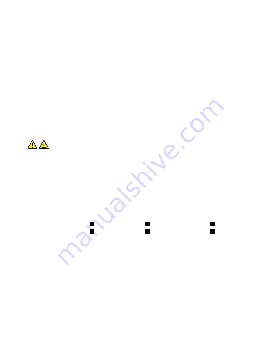
CAUTION:
The heat sink and fan assembly might be very hot. Before you open the computer cover, turn off the
computer and wait several minutes until the computer is cool.
To replace the heat sink and fan assembly, do the following:
1. Prepare your computer. See “Preparing your computer and removing the computer cover” on page 91.
2. Lay the computer on its side for easier access to the system board.
3. Locate the heat sink and fan assembly. See “Major FRUs and CRUs” on page 31.
4. Disconnect the heat sink and fan assembly cable from the microprocessor fan connector on the system
board. See “Parts on the system board” on page 34.
5. Follow the following sequence to remove the four screws that secure the heat sink and fan assembly
to the system board:
a. Partially remove screw
1
, then fully remove screw
2
, and then fully remove screw
1
.
b. Partially remove screw
3
, then fully remove screw
4
, and then fully remove screw
3
.
Note:
Carefully remove the four screws to avoid any possible damage to the system board. The four
screws cannot be removed from the heat sink and fan assembly.
142
P320 Hardware Maintenance Manual
Summary of Contents for ThinsStation P320
Page 1: ...P320 Hardware Maintenance Manual Machine Types 30BG 30BH and 30BR ...
Page 6: ...iv P320 Hardware Maintenance Manual ...
Page 8: ...vi P320 Hardware Maintenance Manual ...
Page 16: ...8 P320 Hardware Maintenance Manual ...
Page 20: ...12 P320 Hardware Maintenance Manual ...
Page 21: ...1 2 Chapter 1 Read this first Important safety information 13 ...
Page 22: ...1 2 14 P320 Hardware Maintenance Manual ...
Page 27: ...1 2 Chapter 1 Read this first Important safety information 19 ...
Page 28: ...1 2 20 P320 Hardware Maintenance Manual ...
Page 31: ...Chapter 1 Read this first Important safety information 23 ...
Page 62: ...54 P320 Hardware Maintenance Manual ...
Page 68: ...60 P320 Hardware Maintenance Manual ...
Page 78: ...70 P320 Hardware Maintenance Manual ...
Page 98: ...90 P320 Hardware Maintenance Manual ...
Page 176: ...168 P320 Hardware Maintenance Manual ...
Page 180: ...172 P320 Hardware Maintenance Manual ...
Page 182: ...174 P320 Hardware Maintenance Manual ...
Page 184: ...176 P320 Hardware Maintenance Manual ...
Page 192: ...184 P320 Hardware Maintenance Manual ...
Page 196: ...188 P320 Hardware Maintenance Manual ...
Page 198: ...190 P320 Hardware Maintenance Manual ...
Page 200: ...192 P320 Hardware Maintenance Manual ...
Page 201: ......
Page 202: ......