• The term “hot-swap drive” refers to all the supported types of hot-swap hard disk drives, hot-swap solid-
state drives, and hot-swap NVMe drives.
• Use any documentation that comes with the drive and follow those instructions in addition to the
instructions in this topic. Ensure that you have all the cables and other equipment that are specified in the
documentation that comes with the drive.
• The electromagnetic interference (EMI) integrity and cooling of the server are protected by having all drive
bays covered or occupied. The vacant bays are either covered by an EMI-protective panel or occupied by
drive fillers. When installing a drive, save the removed drive filler in case that you later remove the drive
and need the drive filler to cover the place.
• To avoid damage to the drive connectors, ensure that the top cover is in place and fully closed whenever
you install or remove a drive.
Remove a hot-swap drive
Use this information to remove a hot-swap drive.
Ground package before opening”
Before removing a hot-swap drive:
1. Ensure that you have backed up data on your drive, especially if it is part of a RAID array.
• Before you make changes to drives, RAID adapters, drive backplanes, or drive cables, back up all
important data that is stored on the drives.
• Before you remove any component of a RAID array, back up all RAID configuration information.
2. If one or more NVMe drives are to be removed, it is recommended to disable them first in Safely Remove
Hardware and Eject Media (Windows) or filesystem (Linux). See the indications above the drive bays to
determine the type of the drive to remove. If the drive bay numbers come with the term “NVMe”, it
indicates the installed drives are NVMe drives.
3. If the security bezel is installed, remove it first. See “Remove the security bezel” on page 99.
Attention:
To ensure that there is adequate system cooling, do not operate the server for more than two
minutes without either a drive or a drive filler installed in each bay.
To remove a hot-swap drive, complete the following steps:
Watch the procedure
. A video of the installation and removal process is available:
• YouTube:
https://www.youtube.com/playlist?list=PLYV5R7hVcs-DTDY1lmpIPpJVOzo7dKq14
• Youku:
http://list.youku.com/albumlist/show/id_52222446.html
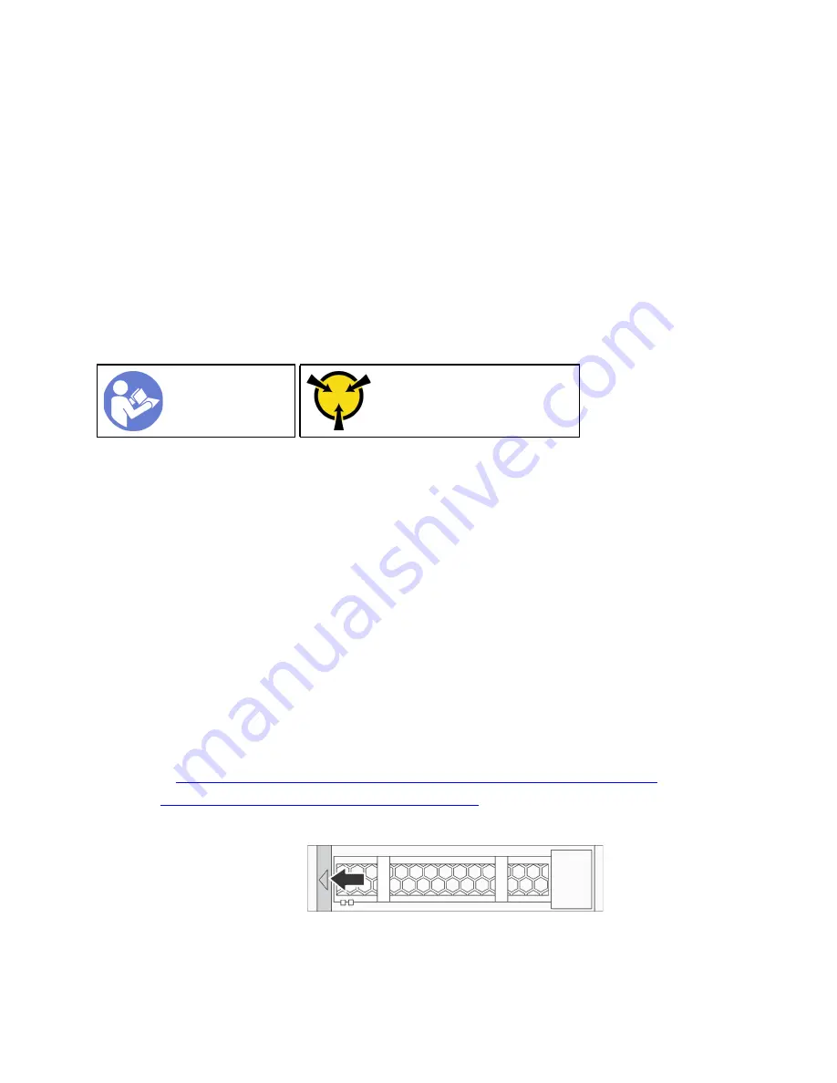
Step 1. Slide the release latch to the left to open the drive tray handle.
Figure 85. Opening the drive tray handle
Step 2. Grasp the handle and slide the drive out of the drive bay.
.
Hardware replacement procedures
111
Summary of Contents for ThinkSystem SR635
Page 1: ...ThinkSystem SR635 Maintenance Manual Machine Types 7Y98 and 7Y99 ...
Page 5: ...Index 231 Copyright Lenovo 2019 2021 iii ...
Page 6: ...iv ThinkSystem SR635 Maintenance Manual ...
Page 10: ...viii ThinkSystem SR635 Maintenance Manual ...
Page 12: ...Figure 2 QR code 2 ThinkSystem SR635 Maintenance Manual ...
Page 22: ...12 ThinkSystem SR635 Maintenance Manual ...
Page 88: ...78 ThinkSystem SR635 Maintenance Manual ...
Page 133: ...Figure 102 Riser 1 assembly LP FHFL removal Chapter 3 Hardware replacement procedures 123 ...
Page 136: ...Figure 105 Riser 1 assembly LP FHFL installation 126 ThinkSystem SR635 Maintenance Manual ...
Page 214: ...204 ThinkSystem SR635 Maintenance Manual ...
Page 232: ...222 ThinkSystem SR635 Maintenance Manual ...
Page 240: ...230 ThinkSystem SR635 Maintenance Manual ...
Page 245: ......
Page 246: ......


