

© Copyright Lenovo 2020
ThinkSystem RAID 940-8i 4GB Flash PCIe Gen4 12Gb Adapter Installation and User
Guide
7
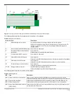
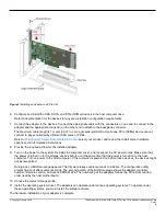
Figure 1
Card Layout for the Thinksystem RAID 940-8i 4GB Flash PCIe Gen4 12Gb Adapter
The following table describes the headers and connectors on the adapter.
Table 2
Headers and Connectors
Connector Type
Description
J2
Standard edge card connector
The interface between the storage adapter and the host system.
With the PCIe interface, this connector provides power to the board and an I
2
C
interface connected to the I
2
C bus for the Intelligent Platform Management
Interface (IPMI).
J4
Default serial boot ROM (SBR) header 2-pin connector. Reserved.
J7
Advanced software options hardware
key header
2-pin connector.
Enables support for selected advanced features.
J8
On-board serial UART connector
4-pin connector. Reserved.
J10
Global HDD activity LED header
2-pin connector.
Connects to an LED that indicates activity on the drives connected to the adapter.
J11
Global drive fault LED header
2-pin connector.
Connects to an LED that indicates whether a drive is in a fault condition.
J14
CacheVault power module interface
9-pin connector.
Connects the adapter to a CacheVault power module.
J17 (C0) Storage interface connector
One SFF-8654 8-port internal connector.
Connect the adapter by cable to the storage devices.
The following table describes the LEDs on the adapter.
Table 3
LED Designations
LED Type
Description
LED 2 Yellow controller over temperature Stays on solid to indicate that the SAS3908 device temperature sensor is over the
temperature threshold. When the device is in the proper temperature range, this LED is off.
LED 3 Green system heartbeat
Indicates that the SAS3908 RoC ASIC is operating normally. This LED blinks at 1 Hz.
LED 5 Yellow supercap fault
Indicates that the CacheVault power module is in fault state or is over temperature.
LED 6 Green Open NAND Flash Interface
(ONFI) activity
Indicates when the ONFI is active for cache offload or recovery. This LED resides on the
nonheat-sink side of the board.