


156 SFP option for CNC ports
D
SFP option for CNC ports
Locate the SFP transceivers
Locate the qualified SFP options for your FC/iSCSI controller canister within your product ship kit. The SFP
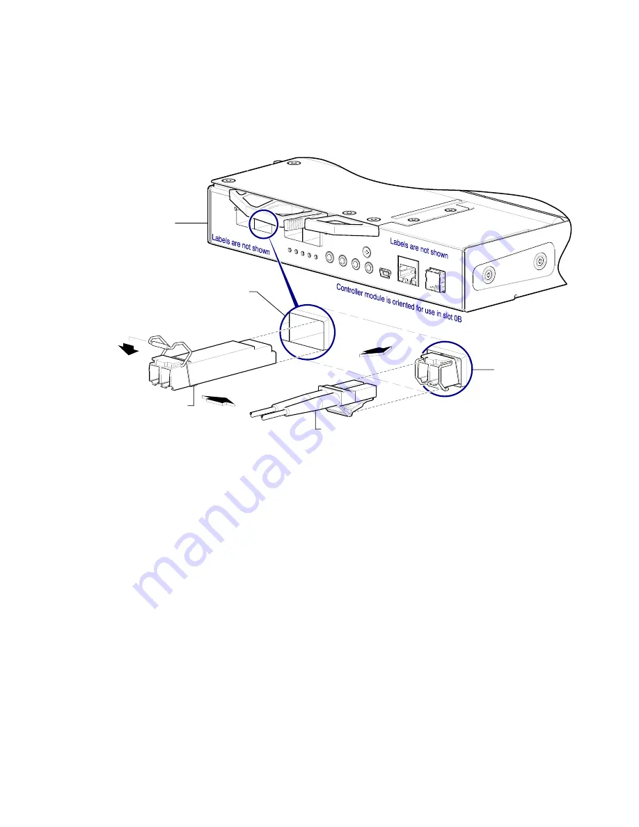
transceiver (SFP) should look similar to the generic SFP shown in the figure below and in
When installing an SFP, refer to the 4-port or 2-port figure that corresponds to your product.
Figure 106 Install a qualified SFP option into an DS4200 or DS6200 FC/iSCSI controller module
Install an SFP transceiver
For each target CNC port, perform the following procedure to install an SFP. Refer to the figure above when
performing the steps. Follow the guidelines provided in
1.
Orient the SFP for the target CNC port and canister position, and align it for insertion.
Depending upon whether the SFP is installed into controller A or B, it will either install right-side up, or upside
down.
2.
If the SFP has a plug, remove it before installing the transceiver. Retain the plug.
3.
Flip the actuator open (sweep up or down) according to the SFP position and alignment for canister slot 0A
(top) or 0B (bottom).
The actuator on your SFP option may look slightly different than the one shown, and it may not open to a sweep
greater than 90° (as shown in the figure above).
4.
Slide the SFP into the target CNC port until it locks securely into place.
5.
Flip the actuator closed (sweep up or down) according to its position in canister slot 0A or 0B.
The installed SFP should look similar to the position shown in the right detail view above.
6.
When ready to attach to the host, obtain and connect a qualified fiber-optic interface cable into the duplex jack
at the end of the SFP connector.
Canister face plate
Target CNC port
Installed SFP
(actuator closed)
Fiber-optic interface cable
Align SFP for installation
(plug removed/actuator open)