background image

Working inside the solution with the power on

You might need to keep the power on with the solution cover removed to look at system information on the 
display panel or to replace hot-swap components. Review these guidelines before doing so.

Attention:

The solution might stop and loss of data might occur when internal solution components are 

exposed to static electricity. To avoid this potential problem, always use an electrostatic-discharge wrist 
strap or other grounding systems when working inside the solution with the power on. 

•  Avoid loose-fitting clothing, particularly around your forearms. Button or roll up long sleeves before 

working inside the solution.

•  Prevent your necktie, scarf, badge rope, or long hair from dangling into the solution.

•  Remove jewelry, such as bracelets, necklaces, rings, cuff links, and wrist watches.

•  Remove items from your shirt pocket, such as pens and pencils, in case they fall into the solution as you 

lean over it.

•  Avoid dropping any metallic objects, such as paper clips, hairpins, and screws, into the solution. 

Handling static-sensitive devices

Review these guidelines before you handle static-sensitive devices to reduce the possibility of damage from 
electrostatic discharge.

Attention:

Prevent exposure to static electricity, which might lead to system halt and loss of data, by 

keeping static-sensitive components in their static-protective packages until installation, and handling these 
devices with an electrostatic-discharge wrist strap or other grounding system.

•  Limit your movement to prevent building up static electricity around you.

•  Take additional care when handling devices during cold weather, for heating would reduce indoor 

humidity and increase static electricity.

•  Always use an electrostatic-discharge wrist strap or other grounding system, particularly when working 

inside the solution with the power on.

•  While the device is still in its static-protective package, touch it to an unpainted metal surface on the 

outside of the solution for at least two seconds. This drains static electricity from the package and from 
your body.

•  Remove the device from the package and install it directly into the solution without putting it down. If it is 

necessary to put the device down, put it back into the static-protective package. Never place the device 
on the solution or on any metal surface. 

•  When handling a device, carefully hold it by the edges or the frame.

•  Do not touch solder joints, pins, or exposed circuitry.

•  Keep the device from others’ reach to prevent possible damages.

Drive replacement

Follow these instructions to replace a front HDD/SSD in the ThinkAgile VX7Y12 Series appliance.

Each ThinkAgile VX7Y12 Series appliance supports solid-state-drives (SSDs) and hard-disk-drives (HDDs).

As user data are striped across these drives, they are referred to as 

data drives

. While a node might be able 

to self-correct for a data drive failure, it does lead to system degradation. To prevent this, always replace 
failed data drives as soon as possible. 

Following are the indications of a failed front HDD/SSD: 

Chapter 8

.

Hardware replacement procedures

49

Summary of Contents for ThinkAgile VX3720 7Y12

Page 1: ...ThinkAgile VX Enclosure ThinkAgile VX3720 User s Guide Machine Type 7Y12 ...

Page 2: ... addition be sure that you are familiar with the terms and conditions of the Lenovo warranty for your solution which can be found at http datacentersupport lenovo com warrantylookup First Edition June 2018 Copyright Lenovo 2018 LIMITED AND RESTRICTED RIGHTS NOTICE If data or software is delivered pursuant to a General Services Administration GSA contract use reproduction or disclosure is subject t...

Page 3: ...ring vCSA manually 39 Adding the ThinkAgile VX7Y12 Series cluster to an existing vCSA instance 39 Chapter 6 Installing and setting up Lenovo XClarity Administrator 41 Deploying Lenovo XClarity Administrator 41 Managing ThinkAgile VX7Y12 Series Servers 42 Chapter 7 Installing and setting up Lenovo XClarity Integrator 45 Deploying Lenovo XClarity Integrator for VMware vCenter 45 Chapter 8 Hardware r...

Page 4: ...Appendix B Getting help and technical assistance 89 Appendix C Trademarks 91 Index 93 ii ThinkAgile VX Enclosure ThinkAgile VX3720 User s Guide ...

Page 5: ...AN deployments Lenovo XClarity Administrator which provides firmware compliance functionality to ensure that the VX7Y14 Series servers are running the appropriate level of firmware for Lenovo XClarity Controller UEFI and PCIe devices Lenovo XClarity Integrator which provides VMware vCenter plug in functionality so that ThinkAgile VX7Y12 Series servers can be managed directly from vCenter The Think...

Page 6: ...nation of solid state disks SSDs for caching and hard disk drives HDDs for storage capacity All Flash Cluster The server provides SSDs for caching and SSDs for storage capacity The following figure provides a conceptual view of the vSAN architecture The following figure provides a conceptual view of the vSAN architecture https storagehub vmware com t vmware vsan vmware r vsan tm design and sizing ...

Page 7: ...mmunicate with the Lenovo XClarity Controller XCC on each of the ThinkAgile VX7Y12 Series servers A redundant 10Gbps Ethernet network is used for VMware vSphere management and vSAN data traffic The redundant Ethernet network is implement through two top of rack switches such as the Lenovo ThinkSystem NE1032 RackSwitch For more information about the Lenovo ThinkSystem NE1032 RackSwitch see the foll...

Page 8: ...nt of the enclosure as shown in the following illustration Figure 1 ID label on the front of the enclosure Table 1 ID label on the front of the enclosure 1 ID label The network access tag can be found on the front of the compute node You can pull way the network access tag to paste your own label for recording some information such as the hostname the system name and the inventory bar code Please ...

Page 9: ...ile PCIe 3 0 x8 adapters from processor 1 PCIe 3 0 x16 shuttle Supports up to four low profile PCIe 3 0 x16 adapters One node supports one low profile PCIe 3 0 x16 adapters from processor 1 Notes 1 PCIe 3 0 x16 shuttle supports PCIe cassettes that can be installed and removed without removing the shuttle from the enclosure 2 Ensure to power off the node before unseating the PCIe cassette from the ...

Page 10: ...imum configuration with four maximal configuration nodes 55 0 kg 121 2 lbs Acoustical noise emissions With the maximum configuration of four nodes with two processors installed full memory installed full drives installed and two 2000 watt power supplies installed Operation 6 8 bels Idle 6 2 bels Heat output based on two 2000 watt power supplies Approximate heat output Minimum configuration with on...

Page 11: ... performance issues Supports the following 2 5 inch hot swap drive backplanes Four 2 5 inch hot swap SAS SATA backplane Six 2 5 inch hot swap SAS SATA backplane Six 2 5 inch hot swap SAS SATA NVMe backplane Important Do not mix nodes with the four drive backplane and six drive backplanes in the same enclosure Mixing the four drive backplane and six drive backplanes may cause unbalanced cooling Hos...

Page 12: ... A2 10 C 35 C 50 F 95 F Above 900 m 2 953 ft de rated maximum air temperature 1 C 300m 984 ft ASHRAE Class A3 5 C 40 C 41 F 104 F Above 900 m 2 953 ft de rated maximum air temperature 1 C 175m 574 ft ASHRAE Class A4 5 C 45 C 41 F 113 F Above 900 m 2 953 ft de rated maximum air temperature 1 C 125m 410 ft Power off4 5 C to 45 C 41 F to 113 F Maximum altitude 3 050 m 10 000 ft Relative Humidity non ...

Page 13: ...ing and a slight drop in performance when ambient is above 27 C 205W processor 28 core or 24 core Intel Xeon 8180 8180M and 8168 200W processor 18 core Intel Xeon 6154 165W processor 12 core Intel Xeon 6146 150W processor 24 core Intel Xeon 8160T 150W processor 8 core Intel Xeon 6144 125W processor 12 core Intel Xeon 6126T Note The listed processors are included but not limited to the above list o...

Page 14: ...nd assign a compliance policy to managed endpoints Lenovo XClarity Administrator monitors changes to the inventory for those endpoints and flags any endpoints that are out of compliance When an endpoint is out of compliance you can use Lenovo XClarity Administrator to apply and activate firmware updates for all devices in that endpoint from a repository of firmware updates that you manage Operatin...

Page 15: ...http www3 lenovo com us en data center software systems management xclarity integrators Chapter 1 Introduction 11 ...

Page 16: ...12 ThinkAgile VX Enclosure ThinkAgile VX3720 User s Guide ...

Page 17: ... proper cooling a node filler has to be installed into every empty node bay in every configuration The enclosure supports up to four compute nodes The following illustration shows the node bays in the enclosure Figure 4 Enclosure front view with compute nodes and node bay numbering Compute node The following illustration shows the controls LEDs and connectors on the front of the compute node Six 2...

Page 18: ...an check event logs to determine the source of the condition When the yellow LED flashes slowly it indicates that the associated drive is being rebuilt When the yellow LED flashes rapidly it indicates that the associated drive is being located Note The hard disk drive status LED might be in a different location on the front of the hard disk drive depending on the drive type that is installed Five ...

Page 19: ...device is connected it indicates it is ready to use and no further action is required Four 2 5 inch drive configuration with KVM breakout module See the following illustration for components connectors and drive bay numbering in four 2 5 inch drive configuration with KVM breakout module Figure 7 Four 2 5 inch drive configuration with KVM breakout module and drive bay numbering Table 6 Components i...

Page 20: ...fy the solution from the rear side see System Management Module SMM on page 18 for more information 4 Power button LED When this LED is lit green it indicates that the node has power This green LED indicates the power status of the compute node Flashing rapidly The LED flashes rapidly for the following reasons The node has been installed in an enclosure When you install the compute node the LED fl...

Page 21: ...er supply 1 4 10Gb 8 port EIOM cage filler 11 System Management Module 5 PCIe slot 3 B 12 PCIe slot 2 B 6 PCIe slot 3 A 13 PCIe slot 2 A 7 PCIe slot 1 A 14 PCIe slot 4 A Note Make sure the power cord is properly connected to every power supply unit installed Shuttle with four low profile PCIe x16 cassette bays Figure 10 Rear view The enclosure with x16 shuttle installed Chapter 2 Solution componen...

Page 22: ...s LED green 4 USB connector 8 System power LED green You can access the dedicated XCC network port of the four nodes via the Ethernet connector on the SMM Go to SMM website and use IP to access XCC For more details see System Management Module User s Guide The following four LEDs on the SMM provide information about SMM operating status 5 System error LED yellow When this LED is lit it indicates t...

Page 23: ...rking correctly the LED flashes at a slower speed about once per second 8 System power LED green When this LED is lit it indicates that the SMM power is on PCIe slot LEDs The following illustration shows the LEDs on the rear of PCIe 3 0 x16 shuttle Figure 12 Rear view PCIe 3 0 x16 LEDs Table 11 PCIe slot LEDs 1 PCIe slot 4 LED 3 PCIe slot 1 LED 2 PCIe slot 3 LED 4 PCIe slot 2 LED These four LEDs p...

Page 24: ...r 11 Trusted cryptographic module TCM connector 4 KVM breakout cable connector 12 KVM breakout module USB connector 5 PCIe slot 1 connector for RAID adapter 13 Processor 2 6 PCIe slot 2 connector 14 Backplane miscellaneous signal connector 7 Processor 1 15 Backplane power connector 8 SATA 1 connector The following illustration shows the location of the DIMM connectors on the system board Figure 14...

Page 25: ... XClarity Controller boot backup Normal default The compute node will boot by using a backup of the XClarity Controller firmware 3 XClarity Controller force update Normal default Enables XClarity Controller force update 4 TPM physical presence Normal default Indicates a physical presence to the system TPM S19 1 System UEFI backup Normal default Enables system BIOS backup 2 Password override jumper...

Page 26: ... shown in the illustrations in this document are reserved Parts list Use the parts list to identify each of the components that are available for your solution Note Depending on the model your solution might look slightly different from in the following illustrations Enclosure components This section includes the components that come with the enclosure 22 ThinkAgile VX Enclosure ThinkAgile VX3720 ...

Page 27: ...Figure 16 Enclosure components The parts listed in the following table are identified as one of the following Chapter 2 Solution components 23 ...

Page 28: ...nt at your request you will be charged for the service Table 14 Parts listing enclosure Index Description Tier 1 CRU Tier 2 CRU FRU Consuma ble and Structural part For more information about ordering the parts shown in Figure 16 enclosure components on page 23 https datacentersupport lenovo com us en products solutions and software thinkagile vx vx3720 7y12 parts 1 10Gb 8 port EIOM cage filler 2 1...

Page 29: ... the parts shown in Figure 17 compute node components on page 25 https datacentersupport lenovo com us en products solutions and software thinkagile vx vx3720 7y12 parts 1 PCIe adapter 2 Air baffle 3 Processor and heat sink assembly 4 Trusted Cryptographic Module 5 M 2 backplane 6 DIMM 7 2 5 inch drive bay blank for empty bays next to the backplane Chapter 2 Solution components 25 ...

Page 30: ...blank panel for drive bays on the backplane 9 2 5 inch hot swap drive 10 Compute node tray 11 KVM breakout module 12 2 5 inch 6 drives hot swap SAS SATA backplane 13 2 5 inch 6 drives hot swap SAS SATA NVMe backplane 14 2 5 inch 4 drives hot swap SAS SATA backplane 15 Compute node cover 26 ThinkAgile VX Enclosure ThinkAgile VX3720 User s Guide ...

Page 31: ...L and certified by the Canadian Standards Association CSA For units intended to be operated at 115 volts Use a UL listed and CSA certified cord set consisting of a minimum 18 AWG Type SVT or SJT three conductor cord a maximum of 15 feet in length and a parallel blade grounding type attachment plug rated 15 amperes 125 volts For units intended to be operated at 230 volts U S use Use a UL listed and...

Page 32: ...28 ThinkAgile VX Enclosure ThinkAgile VX3720 User s Guide ...

Page 33: ... Default Password Virtual Machines VMs IPV4 Host name User ID Password vCenter Server XClarity Adminis trator XClarity Integrator Infrastructure Domain DNS NTP Default Gateway Virtual Network For information about the VMKernal see https docs vmware com en VMware vSphere 6 5 com vmware vsphere networking doc GUID D4191320 209E 4CB5 A709 C8741E713348 html Physical Adapters VMkernal Adapter vSwitch 0...

Page 34: ...VMKernel Adapter Services vMotion Provision ing FT Logging Manage ment vSphere Replica tion vSphere Replica tion NFC vSAN Adapter 1 Adapter 2 30 ThinkAgile VX Enclosure ThinkAgile VX3720 User s Guide ...

Page 35: ...3 Connect the Lenovo XClarity Controller to the management network See Set the network connection for the Lenovo XClarity Controller on page 32 4 If no DHCP server is available to assign IP addresses to the appliances or if you intend to use static IP addresses for the appliances make sure that you assign an IP address to each appliance through ESXi For information about assigning IP addresses thr...

Page 36: ...a standby state power status LED flashes once per second Note The Lenovo XClarity Controller can place the compute node in a standby state as an automatic response to a critical system failure Start an orderly shutdown using the operating system if supported by your operating system Press the power button to start an orderly shutdown if supported by your operating system Press and hold the power b...

Page 37: ... has been configured in the DHCP server Step 4 Click OK to continue starting the server Enable System Management Module network connection via Lenovo XClarity Controller If no KVM breakout module is available to access Lenovo XClarity Controller logs with enable System Management Module network connection via XCC first For more information see Web interface access in System Management Module User ...

Page 38: ...34 ThinkAgile VX Enclosure ThinkAgile VX3720 User s Guide ...

Page 39: ...ce or to install a vCenter instance and deploy a vSAN cluster on a new instance Use the following procedures to download and run the installer Downloading and setting up the ThinkAgile Installer The ThinkAgile Installer is available on the Lenovo website It is downloaded as an OVA template that can be deployed to any vCenter instance or ThinkAgile VX host that is running in your network and that h...

Page 40: ...ver and credentials for the ESXi hosts that are to be used to deploy the VSAN VM data network to which to attach the vCenter Data store to deploy the VM for vCenter User name and password for the vCenter that you want to deploy Ensure that you meet the following prerequisites before running the ThinkAgile Installer All hosts must be powered on and connected to a network that is reachable from the ...

Page 41: ... communication is encrypted However it is signed by a Lenovo certificate authority therefore it is not listed in the trusted certificate chain for your browser The ThinkAgile Installer provides several pages that you can use to specify configuration options for the vSAN deployment License tab Obtaining VMware licenses is your responsibility VMware includes a 60 day trial license but you will need ...

Page 42: ...Configuring vCenter Single Sign On webpage Login credentials Specify the password for the vCenter appliance and whether or not SSH is enabled Review tab On this page all of the settings that you specified are listed for your review Make sure that the settings are correct When you click Next the settings are validated and any issues are displayed for your resolution Click the Back button to make an...

Page 43: ...on process is complete and click Finish 7 After deployment is complete click Continue to begin the Stage 2 installation process setting upvCSA For instructions on deploying the OVA file see the following website Stage 2 Set up the Newly Deployed vCenter Server Appliance with an Embedded Platform Services Controller 8 Create a Datacenter For instructions on creating a Datacenter see the following w...

Page 44: ...3 Add the ThinkAgile VX7Y12 Series hosts to the Cluster 40 ThinkAgile VX Enclosure ThinkAgile VX3720 User s Guide ...

Page 45: ...or Use this information to deploy Lenovo XClarity Administrator Before you begin make sure that you download the Lenovo XClarity Administrator from Lenovo Refer to the ThinkAgile VX Best Recipe to determine the correct version to be downloaded Complete the following steps to deploy Lenovo XClarity Administrator Step 1 Download the Lenovo XClarity Administrator image The currently supported version...

Page 46: ...Information about adding rack views to Lenovo XClarity Administrator is available at http sysmgt lenovofiles com help topic com lenovo lxca doc racks_manage html Step 5 Add the ThinkAgile VX7Y12 Series firmware packages to the Lenovo XClarity Administrator firmware repository From the Lenovo XClarity Administrator web interface you can download install and manage firmware updates for managed Think...

Page 47: ...an existing server to save time Information about creating a server pattern is available at http sysmgt lenovofiles com help topic com lenovo lxca doc server_addserverpattern html Chapter 6 Installing and setting up Lenovo XClarity Administrator 43 ...

Page 48: ...44 ThinkAgile VX Enclosure ThinkAgile VX3720 User s Guide ...

Page 49: ...rs Deploying Lenovo XClarity Integrator for VMware vCenter Use this procedure to install Lenovo XClarity Integrator for VMware vCenter Complete the following steps to deploy Lenovo XClarity Integrator Step 1 Download the Lenovo XClarity Integrator image The currently supported version of Lenovo XClarity Integrator is available at the following website https datacentersupport lenovo com us en solut...

Page 50: ...lenovofiles com help topic com lenovo lxci_vcenter doc vcenter_install_config_lxci html Step 4 Manage the cluster by requesting access to the BMC of each of the servers in the cluster Information about requesting BMC access is available at http sysmgt lenovofiles com help topic com lenovo lxci_vcenter doc vcenter_using_vsphere_web_ client_request_imm_access html 46 ThinkAgile VX Enclosure ThinkAgi...

Page 51: ...p or other grounding system Read the safety information and guidelines to ensure that you work safely A complete list of safety information for all products is available at http thinksystem lenovofiles com help topic safety_documentation pdf_files html The following guidelines are available as well Handling static sensitive devices on page 49 and Working inside the solution with the power on on pa...

Page 52: ...guards labels and ground wires System reliability guidelines Review the system reliability guidelines to ensure proper system cooling and reliability Make sure the following requirements are met When the server comes with redundant power a power supply must be installed in each power supply bay Adequate space around the server must be spared to allow server cooling system to work properly Leave ap...

Page 53: ...trostatic discharge wrist strap or other grounding system Limit your movement to prevent building up static electricity around you Take additional care when handling devices during cold weather for heating would reduce indoor humidity and increase static electricity Always use an electrostatic discharge wrist strap or other grounding system particularly when working inside the solution with the po...

Page 54: ... data that is stored on drives Before you remove any component of a RAID array back up all RAID configuration information If one or more NVMe solid state drives are to be removed disable them beforehand in OS Complete the following steps to remove a drive Step 1 Identify the failed drive to be replaced using the procedure Identify Failed Disk in the VMware Storage and Availability Technical Docume...

Page 55: ... node supports and other information that you must consider when you install a drive For a list of supported drives see http www lenovo com us en serverproven Locate the documentation that comes with the drive and follow those instructions in addition to the instructions in this chapter You can install up to six hot swap SAS SATA 2 5 inch drives for each node The electromagnetic interference EMI i...

Page 56: ...If the green drive activity LED is flashing the drive is being accessed Step 5 If you are installing additional drives do so now After you install all drives complete the following steps 1 If the node is configured for RAID operation using a RAID adapter you might have to reconfigure your disk arrays after you install drives See the RAID adapter documentation for additional information about RAID ...

Page 57: ...ts any equipment that will be attached to this product When possible use one hand only to connect or disconnect signal cables Never turn on any equipment when there is evidence of fire water or structural damage Disconnect the attached power cords telecommunications systems networks and modems before you open the device covers unless instructed otherwise in the installation and configuration proce...

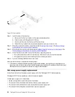
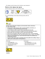
Page 58: ...azardous voltage current and energy levels are present inside any component that has this label attached There are no serviceable parts inside these components If you suspect a problem with one of these parts contact a service technician Before you remove a hot swap power supply 1 Disconnect the power cords and all external cables 2 Identify the failed power supply ThinkAgile VX7Y12 Series applian...

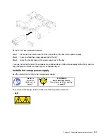
Page 59: ...return the component or optional device follow all packaging instructions and use any packaging materials for shipping that are supplied to you Install a hot swap power supply Use this information to install a hot swap power supply Read the installation Guidelines on page 47 ATTENTION Static Sensitive Device Ground package before opening on page 49 To avoid possible danger read and follow the foll...

Page 60: ...device ON 1 Turn everything OFF 2 First remove power cords from outlet 3 Remove signal cables from connectors 4 Remove all cables from devices S035 CAUTION Never remove the cover on a power supply or any part that has this label attached Hazardous voltage current and energy levels are present inside any component that has this label attached There are no serviceable parts inside these components I...

Page 61: ... s properly connected to the power After installing the hot swap power supply 1 Reconnect any cables that you removed 2 If the node is turned off turn on the node Ensure that the power supply is replaced successfully Amber warning LED on node front panel is off The green indicator light on each power supply is illuminated No errors are shown in the Lenovo XClarity Controller No errors are shown in...

Page 62: ... might cause heating when shorted with metal which might result in spattered metal burns or both Before removing a fan 1 Remove the fan cover see Remove the fan cover Attention Static electricity that is released to internal solution components when the solution is powered on might cause the solution to halt which might result in the loss of data To avoid this potential problem always use an elect...

Page 63: ...emove the fan For a 60x60x56mm fan Squeeze the fan release latches together and then lift the fan out of the enclosure Figure 23 60x60x56mm fan removal For an 80x80x80mm fan 1 Carefully pull the cable out from underneath the sheet metal flange 2 Disconnect the cable 3 Grasp the fan and lift it out of the enclosure Chapter 8 Hardware replacement procedures 59 ...

Page 64: ...s on page 47 ATTENTION Static Sensitive Device Ground package before opening on page 49 To avoid possible danger read and follow the following safety statement S017 CAUTION Hazardous moving fan blades nearby S033 CAUTION Hazardous energy present Voltages with hazardous energy might cause heating when shorted with metal which might result in spattered metal burns or both Before you install a fan 1 ...

Page 65: ...s to install a fan Step 1 Install the fan For a 60x60x56mm fan 1 Lower the fan into the socket and push it downward until it clicks into place Figure 25 60x60x56mm fan installation For an 80x80x80mm fan 1 Lower the fan into the socket and push it downward until it clicks into place 2 Connect the power cable 3 Carefully route the cable underneath the flange and make sure the cable is routed through...

Page 66: ...erformance The hypervisor cannot detect SSDs and HDDs or the red LEDs on the drives are illuminated The hypervisor or BIOS does not detect the HBA card Attention Replacing a RAID adapter might impact your RAID configurations Back up your data before you begin to avoid any data loss due to a RAID configuration change Remove a RAID or HBA adapter Use this information to remove a RAID or HBA adapter ...

Page 67: ...ease latch Step 2 Tilt the adapter to remove it from the node Step 3 Disconnect the SAS SATA cables up to two from the underside of the adapter Step 4 Disconnect the PCIe cable from the underside of the adapter Figure 28 Cable removal If you are instructed to return the component or optional device follow all packaging instructions and use any packaging materials for shipping that are supplied to ...

Page 68: ...A adapter Figure 29 RAID or HBA adapter installation Step 1 Connect the PCIe cable and SAS SATA cables See Internal cable routing Step 2 Insert the end of the adapter into the slot Step 3 Align the adapter with the guide pin then lower and rotate down the adapter to insert it After you install a RAID or HBA adapter into the compute node complete the following steps 1 If the air baffle is removed r...

Page 69: ...he top Phy maps to port one of the system LOM the bottom Phy maps to port two of the system LOM The ports are labeled sequentially from left to right Table 18 EIOM port corresponding node number 1 Ports to node 1 3 Ports to node 3 2 Ports to node 2 4 Ports to node 4 Figure 30 EIOM ports and corresponding node number Remove the EIOM Use this information to remove the EIOM Read the installation Guid...

Page 70: ...l Figure 31 EIOM removal For 10GBASE T cage RJ 45 model Figure 32 EIOM removal Step 1 Disconnect two cables from the EIOM Note Make sure you push the release latch only when disconnecting the signal cable Step 2 Turn the thumbscrews counterclockwise Step 3 Grasp and push the EIOM slightly towards the front side of the shuttle Step 4 Lift the EIOM up to remove the EIOM from the shuttle 66 ThinkAgil...

Page 71: ... 49 Before you install the EIOM touch the static protective package that contains the new EIOM to any unpainted surface on the outside of the server Then take the new EIOM out of the package and place it on a static protective surface Note The minimum networking speed requirement for the EIOM is 1Gbps Complete the following steps to install the EIOM Step 1 Grasp the EIOM and align the four EIOM ta...

Page 72: ...node in the chassis 5 Turn on all compute nodes 6 Exit maintenance mode 7 Check the following to verify whether the EOIM has been successfully replaced The amber warning light on the node front panel is off All the network ports on the EIOM are fully functional PCIe adapter replacement Follow instructions in this section to replace PCIe adapters in the ThinkAgile VX3720 Remove a PCIe adapter Use t...

Page 73: ...ilability Technical Documents Repository 3 Turn off the corresponding compute node that you are going to perform the task on 4 Disconnect the cables from the adapter if any Complete the following steps to remove the PCIe adapter Step 1 Remove the adapter cassette a Slide the release latch to the open position b Slide the adapter cassette out of the shuttle Figure 36 Adapter cassette removal Step 2...

Page 74: ...page 32 ATTENTION Static Sensitive Device Ground package before opening on page 49 Before you install a PCIe adapter 1 Touch the static protective package that contains the adapter to any unpainted metal surface on the solution then remove the adapter from the package 2 Place the adapter component side up on a flat static protective surface and set any jumpers or switches as described by the adapt...

Page 75: ...cassette then insert the adapter into the adapter cassette d Loosen bracket screws for about 1 4 turn to adjust the adapter bracket to secure the adapter according to your adapter length then tighten bracket screws e Fasten the screw to secure the adapter to the cassette f Connect any required cables to the adapter Figure 39 Adapter installation Chapter 8 Hardware replacement procedures 71 ...

Page 76: ...he power cords and any cables that you removed 2 Turn on all compute nodes 3 Exit maintenance mode 4 Verify that the adapter is replaced successfully The amber warning light on the node front panel is off All network ports are fully functional DIMM replacement Use the following procedures to remove and install a DIMM A node might be able to self correct for certain memory errors however failed mem...

Page 77: ...ectly on top of each other during storage Never touch the gold memory module connector contacts or allow these contacts to touch the outside of the memory module connector housing Handle memory modules with care never bend twist or drop a memory module Before you remove a DIMM 1 Identify the failed DIMM by either checking the event logs in UEFI setup or use the Lenovo XClarity Controller web conso...

Page 78: ...n use the Setup utility to view the node configuration information Install higher capacity ranked DIMMs first following the population sequence for the memory mode being used The node supports only industry standard double data rate 4 DDR4 2666 MT s PC4 21300 single rank or dual rank unbuffered or synchronous dynamic random access memory SDRAM dual inline memory modules DIMMs with error correcting...

Page 79: ...ranks in each package rank 8 8 logical ranks in each package rank R rank s xff Device organization data bit width of SDRAMs used on this assembly x4 x4 organization 4 DQ lines per SDRAM x8 x8 organization x16 x16 organization wwwww is the DIMM bandwidth in MBps 2133 2400 2666 2933 3200 aa is the SDRAM speed grade m is the DIMM type E Unbuffered DIMM UDIMM x64 primary 8 bit ECC module data bus L Lo...

Page 80: ...alled 6 3 7 2 8 1 5 4 Processor 1 and 2 installed 6 14 3 11 7 15 2 10 8 16 1 9 5 13 4 12 Memory mirroring population sequence Table 21 DIMM installation sequence mirror mode lockstep mode Number of processors Installation sequence connectors Processor 1 installed 6 7 2 3 8 1 Processor 1 and 2 installed 6 7 14 15 2 3 10 11 1 8 9 16 If you are installing 3 6 9 or 12 identical DIMMs for the mirroring...

Page 81: ...nstalling memory modules Electrostatic discharge gloves can also be used Never hold two or more memory modules together so that they touch Do not stack memory modules directly on top of each other during storage Never touch the gold memory module connector contacts or allow these contacts to touch the outside of the memory module connector housing Handle memory modules with care never bend twist o...

Page 82: ... locked position when the DIMM is firmly seated in the connector Note If there is a gap between the DIMM and the retaining clips the DIMM has not been correctly inserted open the retaining clips remove the DIMM and then reinsert it Step 6 Reconnect any cable that you removed After you install a DIMM complete the following steps 1 Reinstall the air baffle see http thinksystem lenovofiles com help t...

Page 83: ...nes if VMware Distributed Resource Scheduler DRS is not enabled on the cluster 2 Place the node in maintenance mode by following the procedure Enter Maintenance Mode in the VMware Storage and Availability Technical Documents Repository 3 Power off the node and if the cable management arm is not in place disconnect all the cables Pull the node chassis out of the rack 4 Remove the compute node from ...

Page 84: ... M 2 drive out of the package and place them on a static protective surface 2 Adjust the retainer on the M 2 backplane to accommodate the particular size of the M 2 drive you wish to install See Adjust the retainer on the M 2 backplane on page 82 Complete the following steps to install an M 2 drive in the M 2 backplane Step 1 Locate the connector on each side of the M 2 backplane Notes Some M 2 ba...

Page 85: ... compute node cover see Install the compute node cover 3 Reinstall the compute node see Install a compute node in the chassis 4 Check the power LED to make sure it transitions between fast blink and slow blink to indicate the node is ready to be powered on 5 Power on the node 6 Exit maintenance mode 7 Use the Lenovo XClarity Provisioning Manager to configure the RAID For more information see http ...

Page 86: ...he correct keyhole that the retainer should be installed into to accommodate the particular size of the M 2 drive you wish to install To adjust the retainer on the M 2 backplane complete the following steps Figure 49 M 2 retainer adjustment Step 1 Press both sides of the retainer 1 Step 2 Move the retainer forward until it is in the large opening of the keyhole Step 3 Take the retainer out of the ...

Page 87: ... to the target subsystem or device Out of band updates have no dependency on an operating system executing on the core CPU However most out of band operations do require the server to be in the S0 Working power state On Target update The installation or update is initiated from an Operating System executing on the server s operating system Off Target update The installation or update is initiated ...

Page 88: ...r If you need to install a specific update you can use the Lenovo XClarity Controller interface for a specific server Notes To perform an in band update through Windows or Linux the operating system driver must be installed and the Ethernet over USB sometimes called LAN over USB interface must be enabled Additional information about configuring Ethernet over USB is available at http sysmgt lenovof...

Page 89: ...ry for those endpoints and flags any endpoints that are out of compliance Specific details about updating firmware using Lenovo XClarity Administrator are available at http sysmgt lenovofiles com help topic com lenovo lxca doc update_fw html Chapter 9 Updating firmware 85 ...

Page 90: ...86 ThinkAgile VX Enclosure ThinkAgile VX3720 User s Guide ...

Page 91: ...CA To enable DCA 1 From the Lenovo XClarity Provisioning Manager click UEFI Settings System Settings Processors 2 From the DCA drop down list click Enable Set Power Performance Bias To set the power performance biasA 1 From the Lenovo XClarity Provisioning Manager click UEFI Settings System Settings Power 2 From the Power Performance Bias drop down list click Max Performance Modify the Operating M...

Page 92: ... 1 From the Lenovo XClarity Provisioning Manager click UEFI Settings Boot Manager 2 Click Change Boot Order 3 Set the order to a CD DVD Rom b Hard Disk 0 c Network 88 ThinkAgile VX Enclosure ThinkAgile VX3720 User s Guide ...

Page 93: ...echnical assistance or just want more information about Lenovo products use the Lenovo Support Plan for ThinkAgile VX Details for the ThinkAgile VX Support Plan are available at the following site https support lenovo com us en solutions ht505725 on page Copyright Lenovo 2018 89 ...

Page 94: ...90 ThinkAgile VX Enclosure ThinkAgile VX3720 User s Guide ...

Page 95: ... LENOVO and THINKSYSTEM are trademarks of Lenovo Microsoft and Windows are trademarks of the Microsoft group of companies All other trademarks are the property of their respective owners 2018 Lenovo Copyright Lenovo 2018 91 ...

Page 96: ...92 ThinkAgile VX Enclosure ThinkAgile VX3720 User s Guide ...

Page 97: ...lacing 65 EIOM installation 67 EIOM removal 65 enclosure 5 22 enclosure rear view 16 ESXi configure network settings 33 Ethernet 16 link status LED 16 Ethernet activity LED 15 16 Ethernet connector 16 F fan replacing 57 fan install 60 fan remove 58 firmware updates 1 front view connectors 13 LED location 13 front view of the solution 13 G Getting help 89 guidelines options installation 47 system r...

Page 98: ... node 32 power on the compute node 32 power supply replacing 52 power control button 13 power on LED 15 presence detection button 15 Q QR code 4 R RAID HBA adapter replacing 62 RAID HBA adapter installation 64 RAID HBA adapter removal 62 rear view 16 18 19 of the enclosure 16 PCIe 3 0 x16 LEDs 19 System Management Module 18 remove EIOM 65 fan 58 hot swap power supply 53 memory modules 73 PCIe adap...

Page 99: ...nt Module 18 system reliability guidelines 48 system error LED 13 T trademarks 91 U UDIMM requirement 74 Unbuffered DIMM 74 USB connector 13 16 V video connector rear 16 VX3720 5 VX3720 compute node 6 VX7Y12 introduction 1 W warranty 4 working inside the solution power on 49 Copyright Lenovo 2018 95 ...

Page 100: ...96 ThinkAgile VX Enclosure ThinkAgile VX3720 User s Guide ...

Page 101: ......

Page 102: ......

Reviews: