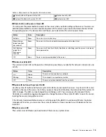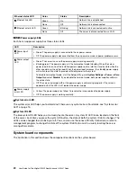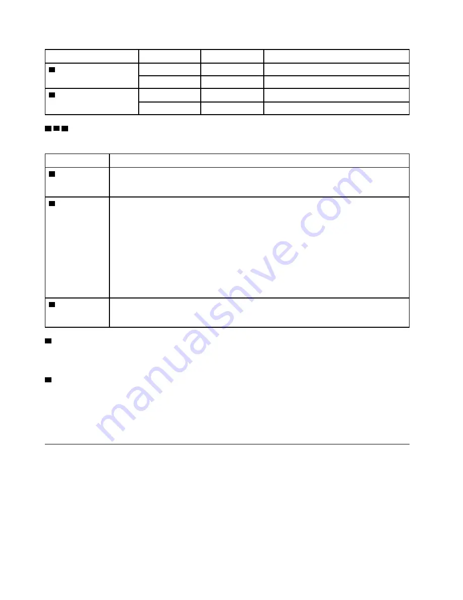
Ethernet status LED
Color
Status
Description
1
Ethernet link LED
Green
On
Network link is established.
None
Off
Network link is disconnected.
2
Ethernet activity LED
Green
Blinking
Network link is connected and active.
None
Off
The server is disconnected from a LAN.
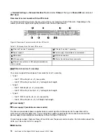
3 4 5
Power supply LEDs
Each hot-swap power supply has three status LEDs.
LED
Description
3
Power input
LED
• Green: The power supply is connected to the ac power source.
• Off: The power supply is disconnected from the ac power source or a power problem occurs.
4
Power output
LED
• Green: The server is on and the power supply is working normally.
• Blinking green: The power supply is in the zero-output mode (standby). When the server
power load is low, one of the installed power supplies enters into the standby state while the
other one delivers the entire load. When the power load increases, the standby power supply
will switch to active state to provide sufficient power to the system.
To disable zero-output mode, start the Setup utility, go to
System Settings
➙
Power
➙
Zero
Output
and select
Disable
. If you disable the zero-out mode, both power supplies will be in
the active state.
• Off: The server is powered off, or the power supply is not working properly. If the server is
powered on but the LED is off, replace the power supply.
5
Power supply
error LED
• Yellow: The power supply has failed. To resolve the issue, replace the power supply.
• Off: The power supply is working normally.
6
System error LED
The system error LED helps you to determine if there are any system errors. For details, see “System error
LED” on page 15.
7
System ID LED
The blue system ID LED helps you to visually locate the server. A system ID LED is also located on the front
of the server. Each time you press the system ID button, the state of both the system ID LEDs changes. The
LEDs can be changed to on, blinking, or off. You can also use the Lenovo XClarity Controller or a remote
management program to change the state of the system ID LEDs to assist in visually locating the server
among other servers.
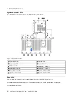
System board components
The illustration in this section shows the component locations on the system board.
20
User Guide for ThinkAgile HX2320 Appliance and HX2321 Node
Summary of Contents for ThinkAgile HX2320 Appliance
Page 4: ...ii User Guide for ThinkAgile HX2320 Appliance and HX2321 Node ...
Page 16: ...12 User Guide for ThinkAgile HX2320 Appliance and HX2321 Node ...
Page 32: ...28 User Guide for ThinkAgile HX2320 Appliance and HX2321 Node ...
Page 38: ...34 User Guide for ThinkAgile HX2320 Appliance and HX2321 Node ...
Page 86: ...82 User Guide for ThinkAgile HX2320 Appliance and HX2321 Node ...
Page 90: ...86 User Guide for ThinkAgile HX2320 Appliance and HX2321 Node ...
Page 92: ...88 User Guide for ThinkAgile HX2320 Appliance and HX2321 Node ...
Page 94: ...90 User Guide for ThinkAgile HX2320 Appliance and HX2321 Node ...
Page 96: ...92 User Guide for ThinkAgile HX2320 Appliance and HX2321 Node ...
Page 99: ......
Page 100: ......

