Server controls, LEDs, and power
Use this information to view power features, turn on and turn off the server, and view the functions of the
controls and indicators.
This section describes the controls and light-emitting diodes (LEDs) and how to turn the server on and off.
For the locations of other LEDs on the system board, see “System-board LEDs” on page 32.
Front view
This section contains information about the controls, LEDs, and connectors on the front of the server.
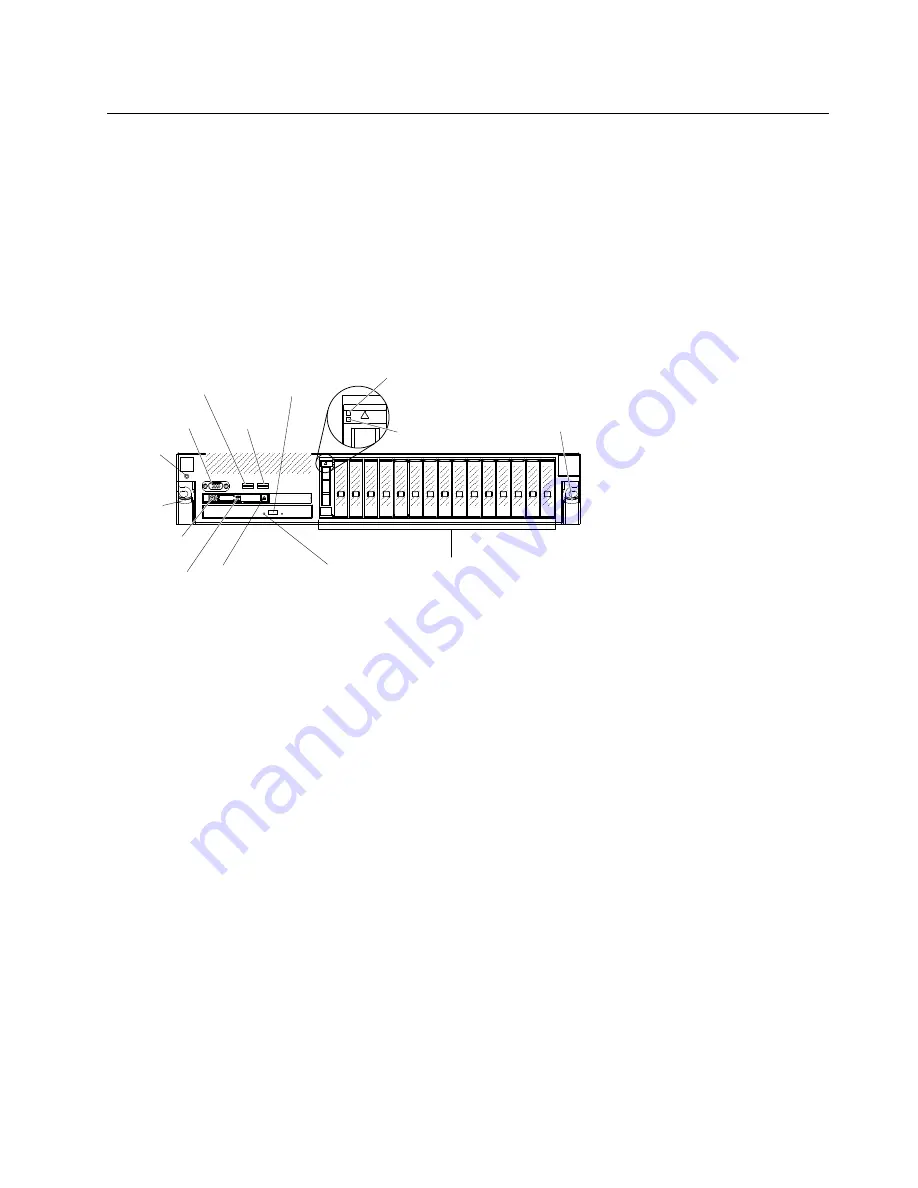
The following illustration shows the controls, LEDs, and connectors on the front of the server.
0
0
0
0
0
0
0
0
0
0
0
0
0
0
0
0
0
0
0
0
0
0
0
0
0
0
0
0
0
0
00000
Video
connector
USB 1
connector
USB 2
connector
0
1
2
3
4
5
6
7
8
9
10
11 12 13 14 15
Drive bays
Rack release
latch
Rack
release
latch
Power-on
button/LED
Locator
button/LED
Operator
information
panel release
latch
CD/DVD drive
activity LED
CD/DVD drive
eject button
Drive activity
LED (green)
Drive status
LED (yellow)
Electrostatic-
discharge
connector
•
Rack release latches:
Press the latch on each front side of the server to slide the server out of the rack.
•
Electrostatic-discharge connector:
Connect an electrostatic-discharge wrist strap to this connector
when you work with static-sensitive devices.
•
Drive status LEDs:
These LEDs are on SAS or SATA hard disk drives and solid state drives. When one of
these LEDs is lit, it indicates that the drive has failed. When this LED is flashing slowly (one flash per
second), it indicates that the drive is being rebuilt. When the LED is flashing rapidly (three flashes per
second), it indicates that the controller is identifying the drive.
•
Drive activity LEDs:
These LEDs are on SAS or SATA hard disk drives and solid state drives. Each
hot-swap drive has an activity LED, and when this LED is flashing, it indicates that the drive is in use.
•
CD/DVD eject button:
Press this button to release a DVD or CD from the CD/DVD drive.
•
CD/DVD drive activity LED:
When this LED is lit, it indicates that the CD-RW/DVD drive is in use.
•
Operator information panel:
This panel contains controls and LEDs that provide information about the
status of the server. For information about the controls and LEDs on the operator information panel, see
“Operator information panel” on page 20.
•
Operator information panel release button:
Press the blue release button and pull out the light path
diagnostics panel to view the light path diagnostics LEDs and buttons. See “Light path diagnostics” on
page 20, “Light path diagnostics” on page 163, and “Light path diagnostics LEDs” on page 166 for
more information about light path diagnostics.
•
Video connector:
Connect a monitor to this connector. The video connectors on the front and rear of
the server can be used simultaneously.
.
The Lenovo System x3750 M4 Type 8753 server
19
Summary of Contents for System x3750 M4
Page 1: ...Lenovo System x3750 M4 Installation and Service Guide Machine Type 8753 ...
Page 6: ...iv Lenovo System x3750 M4 Installation and Service Guide ...
Page 144: ...130 Lenovo System x3750 M4 Installation and Service Guide ...
Page 170: ...156 Lenovo System x3750 M4 Installation and Service Guide ...
Page 319: ...Adapter SAS signal connector SAS signal cable Chapter 6 Removing and replacing components 305 ...
Page 321: ...Adapter SAS signal connector SAS signal cable Chapter 6 Removing and replacing components 307 ...
Page 324: ...8x2 5 inch backplane 310 Lenovo System x3750 M4 Installation and Service Guide ...
Page 492: ...478 Lenovo System x3750 M4 Installation and Service Guide ...
Page 522: ...508 Lenovo System x3750 M4 Installation and Service Guide ...
Page 956: ...942 Lenovo System x3750 M4 Installation and Service Guide ...
Page 960: ...946 Lenovo System x3750 M4 Installation and Service Guide ...
Page 968: ...Taiwan BSMI RoHS declaration 954 Lenovo System x3750 M4 Installation and Service Guide ...
Page 981: ......
Page 982: ...Part Number 00MV562 Printed in China 1P P N 00MV562 1P00MV562 ...


