


Installing the USB cable assembly
Use the information to install the USB cable assembly.
Read the safety information in “Safety” on page v and “Installation guidelines” on page 35.
If you are replacing a server component in the server, you need to turn off the server and peripheral devices,
and disconnect the power cords and all external cables.
To install the USB cable assembly, complete the following steps.
Step 1.
Carefully lay the server down on its side.
Step 2.
Unlock and remove the left-side cover (see “Removing the left-side cover” on page 184).
Step 3.
Remove the air baffle (see “Removing the air baffle” on page 189).
Step 4.
Remove the fan cage assembly (see “Removing the fan cage assembly” on page 272).
Step 5.
Stand the server back up in its vertical position.
Step 6.
Remove the USB cable and light path diagnostics assembly (see “Removing the USB cable and
light path diagnostics assembly” on page 237).
Step 7.
Touch the static-protective package that contains the USB cable assembly to any unpainted metal
surface on the server; then, remove the assembly from the package.
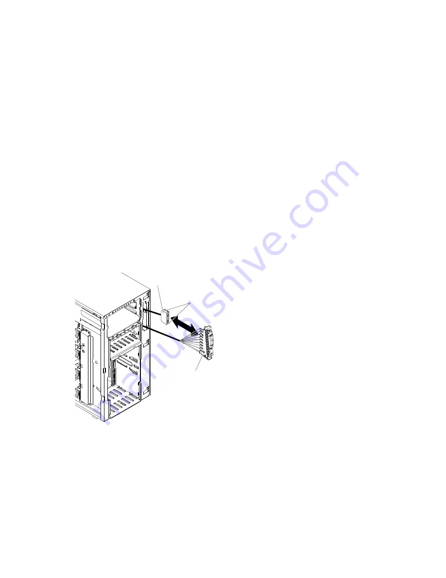
Step 8.
Squeeze the retaining clips on each side of the USB cable connectors and align the key on the
cable connector with the notch on the mounting bracket.
0
0
0
0
0
0
0
0
Front USB
cable assembly
Retention clips
Front USB cable and light path
diagnostics bracket
Figure 159. Squeeze the clips
Step 9.
Insert the USB cable assembly into the mounting bracket; then, release the retaining clips.
Step 10. Position the bottom of the USB cable and light path diagnostics assembly mounting bracket into
the opening and rotate the top of the bracket toward the server until it clicks into place.
Step 11. Install the USB cable and light path diagnostics assembly (see “Installing the USB cable and
light path diagnostics assembly” on page 238).
Step 12. Connect the USB cable to the system board (see “System-board internal connectors” on page
27 and “Internal cable routing and connectors” on page 312).
244
System x3500 M4 Installation and Service Guide
Summary of Contents for System x3500 M4
Page 1: ...System x3500 M4 Installation and Service Guide Machine Type 7383 ...
Page 6: ...iv System x3500 M4 Installation and Service Guide ...
Page 14: ...xii System x3500 M4 Installation and Service Guide ...
Page 140: ...126 System x3500 M4 Installation and Service Guide ...
Page 180: ...166 System x3500 M4 Installation and Service Guide ...
Page 194: ...180 System x3500 M4 Installation and Service Guide ...
Page 978: ...964 System x3500 M4 Installation and Service Guide ...
Page 1002: ...988 System x3500 M4 Installation and Service Guide ...
Page 1160: ...1146 System x3500 M4 Installation and Service Guide ...
Page 1164: ...1150 System x3500 M4 Installation and Service Guide ...
Page 1172: ...Taiwan BSMI RoHS declaration 1158 System x3500 M4 Installation and Service Guide ...
Page 1181: ......
Page 1182: ......


