background image

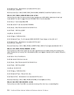
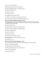
Lock-down code

Description

LL

The controller cannot access either midplane SBB EEPROM.

Ln

A module is not valid for a controller.

LP

Drive port mapping tables are not detected.

Lr

A component that is not a field replaceable unit (FRU) has been replaced.

Lt

A configuration data base corruption has been detected.

LU

The SOD reboot limit has been exceeded.

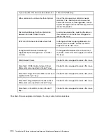
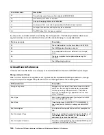
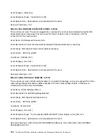
In some cases, controllers detect errors during the startup process. The following table describes seven- 
segment startup errors and conditions that result in the controller being in a suspended state: 

Startup error code

Description

S1

The controller detects a checksum failure in EEPROM.

S2

The SBB Signature/Revision is invalid.

S3

An unsupported enclosure is detected in the storage 
array.

S4

The power supplies are incapable of powering the 
controller.

S5

The SBB pairing has failed.

Critical Events Reference

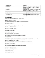
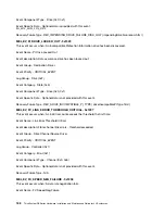
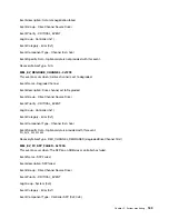
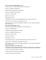
Critical events from DE Series arrays display certain defined fields in the alert and SNMP trap messages.

Storage array alert traps

When a critical Major Event Log (MEL) event is generated, the embedded SNMP agent delivers a storage 
array alert trap to all configured trap destinations. This message contains the following data: 

MIB variable field

Description

Storage array name

Storage array user label. If the label contains non-ASCII 
characters, the resulting variable binding is populated 
with the fixed string "NonASCII Name." If the label is 
blank, the variable binding is populated with the fixed 
string "Unnamed."

Event type

Event Code (4-digit hexadecimal) for the particular MEL 
event that prompted the trap.

Event time

Timestamp of event in MM/DD/YYYY HH:MM:SS (24- 
hour clock) format. Note this is always controller/GMT 
time.

Event description

Description of the specific MEL event that prompted the 
trap.

Event component type

String representation of component type for the MEL vent 
that prompted the trap. Defaults to "Not Available" if 
component type cannot be identified.

Event component location

This data is not populated by the embedded SNMP agent 
running on the controller at this time.

186

ThinkSystem DE Series Hardware Installation and Maintenance Guide for 2U Enclosures

Summary of Contents for DE120S

Page 1: ...ThinkSystem DE Series Hardware Installation and Maintenance Guide for 2U Enclosures Machine Types DE2000H 7Y70 7Y71 DE4000H 7Y74 7Y75 DE4000F 7Y76 DE6000H 7Y78 DE6000F 7Y79 DE120S 7Y63 and DE240S 7Y68 ...

Page 2: ...addition be sure that you are familiar with the terms and conditions of the Lenovo warranty for your server which can be found at http datacentersupport lenovo com warrantylookup First Edition October 2018 Copyright Lenovo 2018 LIMITED AND RESTRICTED RIGHTS NOTICE If data or software is delivered pursuant to a General Services Administration GSA contract use reproduction or disclosure is subject t...

Page 3: ...configuration is supported 51 Configure management port IP addresses 52 Configure the multipath software 52 Install ThinkSystem Storage Manager for SMcli and Host Context Agent HCA 52 Access ThinkSystem System Manager and use the Setup wizard 52 Perform FC specific tasks 54 Perform iSCSI specific tasks 56 Perform SAS specific tasks 61 Discover storage on the host 63 Configure storage on the host 6...

Page 4: ...view 182 Critical Events Reference 186 Appendix A Getting help and technical assistance 277 Appendix B Notices 279 Trademarks 280 Important notes 280 Particulate contamination 280 Telecommunication regulatory statement 281 Electronic emission notices 281 Taiwan BSMI RoHS declaration 282 Taiwan import and export contact information 282 Index 283 ii ThinkSystem DE Series Hardware Installation and Ma...

Page 5: ...eiligheidsvoorschriften Ennen kuin asennat tämän tuotteen lue turvaohjeet kohdasta Safety Information Avant d installer ce produit lisez les consignes de sécurité Vor der Installation dieses Produkts die Sicherheitshinweise lesen Prima di installare questo prodotto leggere le Informazioni sulla Sicurezza Les sikkerhetsinformasjonen Safety Information før du installerer dette produktet Antes de ins...

Page 6: ...e instalar este producto lea la información de seguridad Läs säkerhetsinformationen innan du installerar den här produkten iv ThinkSystem DE Series Hardware Installation and Maintenance Guide for 2U Enclosures ...

Page 7: ... host operating systems DE Series hardware overview The ThinkSystem DE series storage arrays are available in several configurations and models This guide provides installation and maintenance information for 2U models Table 1 DE series family 2U models Family Model Machine Type Form factor Drives DE2000 DE2000H 7Y70 2U 12 DE2000H 7Y71 2U 24 DE4000 DE4000H 7Y74 2U 12 DE4000H 7Y75 2U 24 DE4000F 7Y7...

Page 8: ...H 24 drives Front view of DE4000H 24 drives DE4000F 24 drives DE6000H 24 drives DE6000F 24 drives or DE240S is the same Figure 2 Front view of models with 24 drive bays 1 Operator display panel 2 drive bays For information about the LEDs on the operator display panel see LEDs on the operator display panel on page 176 For information about the LEDs on drives see LEDs on the drives on page 179 2 Thi...

Page 9: ...ement port 3 RJ45 console port 4 HIC host ports 5 Micro B USB console port 6 SAS expansion ports 7 Power supply switch 8 Power fan canister Notes 1 Depending on the configuration the baseboard host ports can be two 10Gb iSCSI optical ports or 16Gb Fiber Channel FC ports 2 There are two Ethernet ports The P1 port is the 1Gb Ethernet management port The P2 port is reserved for Lenovo technical suppo...

Page 10: ...er fan canister Notes 1 Depending on the configuration the baseboard host ports can be two 10Gb iSCSI optical ports or 16Gb FC ports 2 There are two Ethernet ports The P1 port is the 1Gb Ethernet management port The P2 port is reserved for Lenovo technical support 4 Depending on the configuration the optional HIC host ports can be four 12Gb SAS ports 10Gb iSCSI optical ports 16Gb FC ports 10 25Gb ...

Page 11: ...al ports or 16Gb FC ports 2 There are two Ethernet ports The P1 port is the 1Gb Ethernet management port The P2 port is reserved for Lenovo technical support 4 Depending on the configuration the optional HIC host ports can be four 12Gb SAS ports 10 25Gb iSCSI optical ports or 32Gb FC ports For information about the LEDs on the rear view see LEDs on the rear of controllers on page 174 and LEDs on t...

Page 12: ...2 5 inch SAS SSD HDD drives in a 3 5 inch adapter tray System Maximums and Limits Max raw capacity 576 TB Max HDD drive count 48 Max SSD drive count 48 Max expansion shelf count 3 Max volume count 512 Max drives per disk pool 48 Max disk pool volumes 512 Max Vol size for a disk pool volume TB 857 Max disk pools 20 Max partitions 128 Max volumes per partition 256 Flash read cache Min Max SSD SLC ML...

Page 13: ...torage or shipping 40 C to 70 C 40 F to 158 F Relative humidity Operating 20 80 Storage 5 95 Shipping 10 95 Altitude range Operating 0 m to 3048 m 0 ft to 10000 ft Storage 305 m to 12 192 m 1000 ft to 39990 ft Note If you plan to operate a system at an altitude between 3280 ft to 9842 ft 1000 m to 3000 m above sea level lower the environmental temperature 3 1 F 1 7 C for every 3280 ft 1000 m above...

Page 14: ...x drives per disk pool 96 Max disk pool volumes 512 Max Vol size for a disk pool volume TB 789 Max disk pools 20 Max partitions 128 Max volumes per partition 256 Flash read cache Min Max SSD SLC MLC 400 5120 GB Max destaging cache to flash size 8 GB Interfaces Available with the following interfaces 16Gb Fibre Channel 12Gb SAS 10Gb iSCSI optical 10Gb iSCSI BaseT RJ 45 System clearance dimension Th...

Page 15: ... 158 F Relative humidity Operating 20 80 Storage 5 95 Shipping 10 95 Altitude range Operating 0 m to 3048 m 0 ft to 10000 ft Storage 305 m to 12 192 m 1000 ft to 39990 ft Note If you plan to operate a system at an altitude between 3280 ft to 9842 ft 1000 m to 3000 m above sea level lower the environmental temperature 3 1 F 1 7 C for every 3280 ft 1000 m above sea level Chapter 1 Introduction 9 ...

Page 16: ...ves in a 3 5 inch adapter tray System Maximums and Limits Max raw capacity 1 15 PB Max drive count 96 Max SSD drive count 96 Max expansion shelf count 7 Max volume count 512 Max drives per disk pool 96 Max disk pool volumes 512 Max Vol size for a disk pool volume TB 857 Max disk pools 20 Max partitions 128 Max volumes per partition 256 Flash read cache Min Max SSD SLC MLC 400 5120 GB Max destaging...

Page 17: ...158 F Relative humidity Operating 20 80 Storage 5 95 Shipping 10 95 Altitude range Operating 0 m to 3048 m 0 ft to 10000 ft Storage 305 m to 12 192 m 1000 ft to 39990 ft Note If you plan to operate a system at an altitude between 3280 ft to 9842 ft 1000 m to 3000 m above sea level lower the environmental temperature 3 1 F 1 7 C for every 3280 ft 1000 m above sea level Chapter 1 Introduction 11 ...

Page 18: ...20 DE4000F 192 Max external shelf count 7 Max volume count 512 Max drives per disk pool 192 Max disk pool volumes 512 Max Vol size for a disk pool volume TB 789 Max disk pools 20 Max partitions 128 Max volumes per partition 256 Flash read cache Min Max SSD SLC MLC 400 5120 GB Max destaging cache to flash size 8 GB Interfaces Available with the following interfaces 16Gb or 32Gb Fibre Channel 12Gb S...

Page 19: ... F to 158 F Relative humidity Operating 20 80 Storage 5 95 Shipping 10 95 Altitude range Operating 0 m to 3048 m 0 ft to 10000 ft Storage 305 m to 12 192 m 1000 ft to 39990 ft Note If you plan to operate a system at an altitude between 3280 ft to 9842 ft 1000 m to 3000 m above sea level lower the environmental temperature 3 1 F 1 7 C for every 3280 ft 1000 m above sea level Chapter 1 Introduction ...

Page 20: ...and Limits Max raw capacity 345 6 TB Max HDD drive count 192 Max SSD drive count 120 Max external shelf count 7 Max volume count 2048 Max drives per disk pool 192 Max disk pool volumes 2048 Max Vol size for a disk pool volume TB 14559 Max disk pools 20 Max partitions 512 Max volumes per partition 256 Flash read cache Min Max SSD SLC MLC 400 5120 GB Max destaging cache to flash size 8 GB Interfaces...

Page 21: ...torage or shipping 40 C to 70 C 40 F to 158 F Relative humidity Operating 20 80 Storage 5 95 Shipping 10 95 Altitude range Operating 0 m to 3048 m 0 ft to 10000 ft Storage 305 m to 12 192 m 1000 ft to 39990 ft Note If you plan to operate a system at an altitude between 3280 ft to 9842 ft 1000 m to 3000 m above sea level lower the environmental temperature 3 1 F 1 7 C for every 3280 ft 1000 m above...

Page 22: ... size for a disk pool volume TB 14559 Max disk pools 20 Max partitions 512 Max volumes per partition 256 Flash read cache Min Max SSD SLC MLC 400 5120 GB Max destaging cache to flash size 8 GB Interfaces Available with the following interfaces 16Gb or 32Gb Fibre Channel 12Gb SAS 10Gb or 25Gb iSCSI System clearance dimension The clearance needed for proper ventilation and heat dissipation is as fol...

Page 23: ...158 F Relative humidity Operating 20 80 Storage 5 95 Shipping 10 95 Altitude range Operating 0 m to 3048 m 0 ft to 10000 ft Storage 305 m to 12 192 m 1000 ft to 39990 ft Note If you plan to operate a system at an altitude between 3280 ft to 9842 ft 1000 m to 3000 m above sea level lower the environmental temperature 3 1 F 1 7 C for every 3280 ft 1000 m above sea level Chapter 1 Introduction 17 ...

Page 24: ... mounting flanges 480 mm 18 9 inches Without mounting flanges 447 mm 17 6 inches Depth With cable management arm 534 mm 21 02 inches Without cable management arm 505 mm 19 88 inches Weight 16 kg 35 27 lb Supported drives 3 5 inch NL SAS drives 2 5 inch SAS SSD HDD drives System clearance dimension The clearance needed for proper ventilation and heat dissipation is as follows Front For cooling 153 ...

Page 25: ...70 C 40 F to 158 F Relative humidity Operating 20 80 Storage 5 95 Shipping 10 95 Altitude range Operating 0 m to 3045 m 0 ft to 9988 ft Storage 305 m to 12 192 m 1000 ft to 39990 ft Note If you plan to operate a system at an altitude between 3280 ft to 9842 ft 1000 m to 3000 m above sea level lower the environmental temperature 3 1 F 1 7 C for every 3280 ft 1000 m above sea level Chapter 1 Introdu...

Page 26: ...ches Rear For cooling 610 mm 24 02 inches For maintenance 305 mm 12 01 inches Power input Input power voltage Low range 100 120 V ac High range 200 240 V ac Environment requirements Air temperature Operating 10 C to 40 C 50 F to 104 F Storage or shipping 40 C to 70 C 40 F to 158 F Relative humidity Operating 20 80 Storage 5 95 Shipping 10 95 Altitude range Operating 0 m to 3045 m 0 ft to 9988 ft S...

Page 27: ...ler To access the user interface point a browser to the controller s IP address A setup wizard helps you get started with system configuration As an alternative you can also use the command line interface CLI Select the interface you want to use ThinkSystem System Manager online help Command Line Interface CLI Reference System Manager offers a variety of management features including Performance V...

Page 28: ...kSystem SAN Manager hereinafter called SAN Manager SAN Manager is web based software used for managing your entire domain From a central view you can view status of all storage arrays connected to a host and you can perform batch operations on selected storage arrays For detailed information about SAN Manager go to ThinkSystem SAN Manager online help ThinkSystem Storage Manager The ThinkSystem Sto...

Page 29: ...nd running with your system you install hardware components configure host systems and configure storage Deploying the storage array involves the following workflow Figure 7 Setup workflow Step 1 Install hardware To install the system hardware refer to the Installation and Setup Instructions that comes with your system Copyright Lenovo 2018 23 ...

Page 30: ...s IP address A setup wizard helps you get started with system configuration As an alternative you can also use the command line interface CLI Select the interface you want to use ThinkSystem System Manager online help Command Line Interface CLI Reference Cabling your storage system You can cable a host directly to a controller or use switches to connect a host to a controller If your storage syste...

Page 31: ... controllers in your storage system The following figure shows an example connection To help ensure maximum performance make sure to use all available host adapter ports Two hosts and two controllers Connect each host adapter port directly to the host ports on the controllers Cabling for a switch topology A topology that uses switches to connect hosts to the controllers in your storage system must...

Page 32: ...rive shelf cabling You must connect each controller in the controller shelf to an Input Output module IOM in a drive shelf Cabling a 12 drive or 24 drive shelf You can cable your controller shelf to one or more 12 drive or 24 drive shelves with SAS 3 drives 26 ThinkSystem DE Series Hardware Installation and Maintenance Guide for 2U Enclosures ...

Page 33: ...fferent power distribution units PDUs in the cabinet or rack Hot adding a drive shelf You can add a new drive shelf while power is still applied to the other components of the storage system You can configure reconfigure add or relocate storage system capacity without interrupting user access to data To maintain system integrity you must follow the procedure exactly in the order presented Prepare ...

Page 34: ...ing conditions exist The number of ESMs IOMs detected matches the number of ESMs IOMs installed in the system and that for each drive shelf Both of the ESMs IOMs show that communication is OK The data rate is 12Gb s for DE120S DE240S and DE600S drive shelves Go to Install the drive shelf Install the drive shelf and apply power You install a new drive shelf or a previously installed drive shelf tur...

Page 35: ... the controller shelf Step 3 Scroll down as necessary to see all the drive shelves in the new storage system If the new drive shelf is not displayed resolve the connection issue Step 4 Select the ESMs IOMs icon for the new drive shelf The Shelf Component Settings dialog box appears Step 5 Select the ESMs IOMs tab in the Shelf Component Settings dialog box Step 6 Select Show more options and verify...

Page 36: ...the link and resolve any issues indicated in the Recovery Guru Step 3 In ThinkSystem System Manager click Hardware and scroll down as necessary to see the newly added drive shelf Step 4 For drives that were previously installed in a different storage system add one drive at time to the newly installed drive shelf Wait for each drive to be recognized before you insert the next drive When a drive is...

Page 37: ...t topology A direct topology connects your controller directly to an Ethernet network Note You must connect management port 1 on each controller for out of band management and leave port 2 available for access to the storage array by technical support Direct storage management connections Switch topology A switch topology uses a switch to connect your controller to an Ethernet network Note You mus...

Page 38: ...st to a DE Series system It is designed to get the storage system up and running as quickly as possible with minimal decision points The express method includes the following steps 1 Setting up one of the following communication environments Fibre Channel FC iSCSI SAS 2 Creating logical volumes on the storage array and assigning a logical unit number LUN to each volume 3 Making the volume LUNs ava...

Page 39: ...management in which a storage management station sends commands to the storage array through the Ethernet connections to the controller You have attached the management station to the same subnet as the storage management ports IP addressing You have not yet made an Ethernet connection between the management station and the storage array Storage provisioning You will not use shared volumes You wil...

Page 40: ...teroperability Matrix document and click to download or view the file In this file you may search for the product family that applies as well as other criteria for the configuration such as Operating System ThinkSystem SAN OS and Host Multipath driver Step 4 As necessary make the updates for your operating system and protocol as listed in the table Operating system updates Protocol Protocol relate...

Page 41: ...tallations use the native MPIO Device Specific Module DSM driver for failover When you install ThinkSystem Storage Manager the DSM driver is installed and enabled You do not need to take further action to use multipath Installing ThinkSystem Storage Manager Perform the following steps to install ThinkSystem Storage Manager and use the multipath package for Windows Before you begin You must have th...

Page 42: ...em Storage Manager client has the following minimum requirements RAM 2 GB for Java Runtime Engine Disk space 5 GB OS Architecture Refer to DE Series Product Support Site Drivers Software Product Firmware for guidance on determining the supported operating system versions and architectures Step 1 Download the ThinkSystem Storage Manager software release from DE Series Product Support Site Drivers S...

Page 43: ... support security and monitor The latter three roles have random passwords that cannot be guessed After you set a password for the admin role you can change all of the passwords using the admin credentials See ThinkSystem System Manager online help for more information on the four local user roles Step 2 Enter the System Manager password for the admin role in the S Se et t A Ad dm miin niis st tr ...

Page 44: ...e that includes the first host initiator port and that also includes all of the target ports that connect to the same FC switch as the initiator Step 3 Create additional zones for each FC host initiator port in the switch Step 4 Save the zones and then activate the new zoning configuration Determining host WWPNs and making the recommended settings FC Windows You install an FC HBA utility so you ca...

Page 45: ...as two paths to the storage one to each controller Host identifiers Callout No Host initiator port connections WWPN 1 Host not applicable 2 Host port 0 to FC switch zone 0 7 Host port 1 to FC switch zone 1 Target identifiers Callout No Array controller target port connections WWPN 3 Switch not applicable 6 Array controller target not applicable 5 Controller A port 1 to FC switch 1 9 Controller A p...

Page 46: ...rements Consult your network administrator for tips on selecting the best configuration for your environment An effective strategy for configuring the iSCSI network with basic redundancy is to connect each host port and one port from each controller to separate switches and partition each set of host and controller ports on separate network segments using VLANs You must enable send and receive har...

Page 47: ...entials When you open System Manager and no pools volumes groups workloads or notifications have been configured the Setup wizard launches Step 3 Close the Setup wizard You will use the wizard later to complete additional setup tasks Step 4 Select Hardware Step 5 If the graphic shows the drives click Show back of shelf The graphic changes to show the controllers instead of the drives Step 6 Click ...

Page 48: ...P address and router IP address Enable VLAN support Available by clicking Show more settings Important This option is only available in an iSCSI environment Select this option to enable a VLAN and enter its ID A VLAN is a logical network that behaves like it is physically separate from other physical and virtual local area networks LANs supported by the same switches the same routers or both Enabl...

Page 49: ... first target portal you discovered and then select Connect Step 5 Select Enable multi path select Add this connection to the list of Favorite Targets and then select Advanced Step 6 For Local adapter select Microsoft iSCSI Initiator Step 7 For Initiator IP select the IP address of a port on the same subnet or VLAN as one of the iSCSI targets Step 8 For Target IP select the IP address of a port on...

Page 50: ...IP_address In this example the iSCSI target IP address is 192 0 2 8 C ping l 8972 f 192 0 2 8 Pinging 192 0 2 8 with 8972 bytes of data Reply from 192 0 2 8 bytes 8972 time 2ms TTL 64 Reply from 192 0 2 8 bytes 8972 time 2ms TTL 64 Reply from 192 0 2 8 bytes 8972 time 2ms TTL 64 Reply from 192 0 2 8 bytes 8972 time 2ms TTL 64 Ping statistics for 192 0 2 8 Packets Sent 4 Received 4 Lost 0 0 loss Ap...

Page 51: ...ation to perform provisioning tasks Recommended configuration Recommended configurations consist of two initiator ports and four target ports with one or more VLANs Target IQN Callout No Target port connection IQN 2 Target port Mappings host name Callout No Host information Name and type 1 Mappings host name Host OS type Perform SAS specific tasks For the SAS protocol you determine host port addre...

Page 52: ...sas3flash 12G utility Host I O ports might automatically register if the host context agent is installed Step 1 Download the LSI sas2flash 6G or sas3flash 12G utility from your HBA vendor s web site Step 2 Install the utility Step 3 Use the HBA BIOS to select the appropriate settings for your configuration Go to DE Series Product Support Site click on the Documentation tab and look for the Interop...

Page 53: ...plicable 2 Host initiator port 1 connected to Controller A port 1 3 Host initiator port 1 connected to Controller B port 1 4 Host initiator port 2 connected to Controller A port 1 5 Host initiator port 2 connected to Controller B port 1 Target Identifiers Recommended configurations consist of two target ports Mappings Host Mappings Host Name Host OS Type Discover storage on the host LUNs on your s...

Page 54: ...st of available disks list disk Step 3 Select the disk to bring online select disk 1 Step 4 Bring the disk online online disk Step 5 Create a partition create partition primary Note In Windows Server 2008 and later you are prompted immediately after creating the partition to format the disk and give it a name Select Cancel on the prompt to continue using these instructions for formatting and namin...

Page 55: ...r setting up a standalone VMware host to a DE Series storage system It is designed to get the storage system up and running as quickly as possible with minimal decision points The express method includes the following steps 1 Setting up one of the following communication environments Fibre Channel FC iSCSI SAS 2 Creating logical volumes on the storage array and assigning a logical unit number LUN ...

Page 56: ...e storage array Storage provisioning You will not use shared volumes You will create pools rather than volume groups Protocol FC You have made all host side FC connections and activated switch zoning You are using Lenovo supported FC HBAs and switches You are using FC HBA driver versions as listed on the DE Series Product Support Site Protocol iSCSI You are using Ethernet switches capable of trans...

Page 57: ...tep 3 Look for the Interoperability Matrix document and click to download or view the file In this file you may search for the product family that applies as well as other criteria for the configuration such as Operating System ThinkSystem SAN OS and Host Multipath driver Step 4 As necessary make the updates for your operating system and protocol as listed in the table Operating system updates Pro...

Page 58: ...System Storage Manager for SMcli and Host Context Agent HCA When you install the ThinkSystem Storage Manager software on your management station the command line interface CLI is installed to help you manage your array By also installing the software on the host the Host Context Agent is installed that helps the host push configuration information to the storage array controllers through the I O p...

Page 59: ... support security and monitor The latter three roles have random passwords that cannot be guessed After you set a password for the admin role you can change all of the passwords using the admin credentials See ThinkSystem System Manager online help for more information on the four local user roles Step 2 Enter the System Manager password for the admin role in the S Se et t A Ad dm miin niis st tr ...

Page 60: ...t Each initiator port must be in a separate zone with all of its corresponding target ports Step 1 Log in to the FC switch administration program and then select the zoning configuration option Step 2 Create a new zone that includes the first host initiator port and that also includes all of the target ports that connect to the same FC switch as the initiator Step 3 Create additional zones for eac...

Page 61: ...as two paths to the storage one to each controller Host identifiers Callout No Host initiator port connections WWPN 1 Host not applicable 2 Host port 0 to FC switch zone 0 7 Host port 1 to FC switch zone 1 Target identifiers Callout No Array controller target port connections WWPN 3 Switch not applicable 6 Array controller target not applicable 5 Controller A port 1 to FC switch 1 9 Controller A p...

Page 62: ...VMware Configuration Maximums guides state that the maximum supported iSCSI storage paths is 8 You must consider this requirement to avoid configuring too many paths By default the VMware iSCSI software initiator creates a single session per iSCSI target when you are not using iSCSI port binding Note VMware iSCSI port binding is a feature that forces all bound VMkernel ports to log into all target...

Page 63: ...d on an array that has not been configured the S Se et t A Ad dm miin niis st tr ra at to or r P Pa as ss sw wo or rd d prompt appears Role based access management configures four local roles admin support security and monitor The latter three roles have random passwords that cannot be guessed After you set a password for the admin role you can change all of the passwords using the admin credentia...

Page 64: ...ue between 1500 and 9000 Enable ICMP PING responses Select this option to enable the Internet Control Message Protocol ICMP The operating systems of networked computers use this protocol to send messages These ICMP messages determine whether a host is reachable and how long it takes to get packets to and from that host If you selected Enable IPv4 a dialog box opens for selecting IPv4 settings afte...

Page 65: ...th the array In this express method for configuring iSCSI networking on the host side you allow the ESXi host to carry iSCSI traffic over four redundant paths to the storage After you complete this task the host is configured with a single vSwitch containing both VMkernel ports and both VMNICs For additional information on configuring iSCSI networking for VMware see the vSphere Documentation Cente...

Page 66: ...Ping statistics for 192 0 2 8 Packets Sent 4 Received 4 Lost 0 0 loss Approximate round trip times in milli seconds Minimum 2ms Maximum 2ms Average 2ms Step 2 Issue a v vm mk kp piin ng g command from each host s initiator address the IP address of the host Ethernet port used for iSCSI to each controller iSCSI port Perform this action from each host server in the configuration changing the IP addr...

Page 67: ...tion to perform provisioning tasks Recommended configuration Recommended configurations consist of two initiator ports and four target ports with one or more VLANs Target IQN Callout No Target port connection IQN 2 Target port Mappings host name Callout No Host information Name and type 1 Mappings host name Host OS type Perform SAS specific tasks For the SAS protocol you determine host port addres...

Page 68: ...as3flash 12G utility Host I O ports might automatically register if the host context agent is installed Step 1 Download the LSI sas2flash 6G or sas3flash 12G utility from your HBA vendor s web site Step 2 Install the utility Step 3 Use the HBA BIOS to select the appropriate settings for your configuration Go to DE Series Product Support Site click on the Documentation tab and look for the Interope...

Page 69: ...nnections SAS address 1 Host not applicable 2 Host initiator port 1 connected to Controller A port 1 3 Host initiator port 1 connected to Controller B port 1 4 Host initiator port 2 connected to Controller A port 1 5 Host initiator port 2 connected to Controller B port 1 Target Identifiers Recommended configurations consist of two target ports Mappings Host Mappings Host Name Host OS Type Discover...

Page 70: ... datastores using either the vSphere Client or the vSphere Web Client see the VMware pubs webpage https www vmware com support pubs for documentation on this topic For instructions on using volumes as RDMs using either the vSphere Client or the vSphere Web Client see the VMware pubs webpage https www vmware com support pubs for documentation on this topic Verify storage access on the host Before y...

Page 71: ...ade an Ethernet connection between the management station and the storage array Storage provisioning You will not use shared volumes You will create pools rather than volume groups Protocol FC You have made all host side FC connections and activated switch zoning You are using Lenovo supported FC HBAs and switches You are using FC HBA driver versions as listed on the DE Series Product Support Site...

Page 72: ... have the correct administrator or superuser privileges You must have ensured that the system that will contain the ThinkSystem Storage Manager client has the following minimum requirements RAM 2 GB for Java Runtime Engine Disk space 5 GB OS Architecture Refer to DE Series Product Support Site Drivers Software Product Firmware for guidance on determining the supported operating system versions and...

Page 73: ...onfigures four local roles admin support security and monitor The latter three roles have random passwords that cannot be guessed After you set a password for the admin role you can change all of the passwords using the admin credentials See ThinkSystem System Manager online help for more information on the four local user roles Step 2 Enter the System Manager password for the admin role in the S ...

Page 74: ...ready installed the operating system use the media supplied by your operating system vendor Step 1 If a multipath conf file is not already created run the t to ou uc ch h e et tc c m mu ullt tiip pa at th h c co on nf f command Step 2 Use the default multipath settings by leaving the multipath conf file blank Step 3 Start the multipath service systemctl start multipathd Step 4 Configure multipath ...

Page 75: ...tep 1 Log in to the FC switch administration program and then select the zoning configuration option Step 2 Create a new zone that includes the first host initiator port and that also includes all of the target ports that connect to the same FC switch as the initiator Step 3 Create additional zones for each FC host initiator port in the switch Step 4 Save the zones and then activate the new zoning...

Page 76: ...C Active Active UTM LUN None LUN 116 LUN Size Product DE Series Host Device mpathr 360080e50004300ac000007575568851d Multipath Policy round robin 0 Multipath Provider Native host controller controller path path dev host target state type node adapter port up secondary sdcx host14 A1 up secondary sdat host10 A2 up secondary sdbv host13 B1 Step 2 Create a new partition according to the method approp...

Page 77: ...t copy one or more files to the mount point of the disk Step 2 Copy the files back to a different folder on the original disk Step 3 Run the d diif ff f command to compare the copied files to the originals Remove the file and folder that you copied Chapter 2 System setup and configuration 71 ...

Page 78: ...blue line the other zone is indicated by the red line Any single port has two paths to the storage one to each controller Host identifiers Callout No Host initiator port connections WWPN 1 Host not applicable 2 Host port 0 to FC switch zone 0 7 Host port 1 to FC switch zone 1 Target identifiers Callout No Array controller target port connections WWPN 3 Switch not applicable 6 Array controller targ...

Page 79: ...gure your management port refer to the Installation and Setup Instructions that comes with your system Install ThinkSystem Storage Manager for SMcli and Host Context Agent HCA When you install the ThinkSystem Storage Manager software on your management station the command line interface CLI is installed to help you manage your array By also installing the software on the host the Host Context Agen...

Page 80: ...ollowing browsers Browser Minimum version Google Chrome 47 Microsoft Internet Explorer 11 Microsoft Edge EdgeHTML 12 Mozilla Firefox 31 Safari 9 You are using out of band management The wizard automatically relaunches when you open System Manager or refresh your browser and at least one of the following conditions is met No pools and volume groups are detected No workloads are detected No notifica...

Page 81: ...array in case one of the physical paths is disrupted The multipath software presents the operating system with a single virtual device that represents the active physical paths to the storage The multipath software also manages the failover process that updates the virtual device You use the device mapper multipath DM MP tool for Linux installations Before you begin You have installed the required...

Page 82: ...host type to the appropriate setting Step 10 Reboot the host Determine SAS host identifiers Linux For the SAS protocol you find the SAS addresses using the HBA utility then use the HBA BIOS to make the appropriate configuration settings Guidelines for HBA utilities Most HBA vendors offer an HBA utility Depending on your host operating system and CPU use either the LSI sas2flash 6G or sas3flash 12G...

Page 83: ...rding to the method appropriate for your Linux OS release Typically characters identifying the partition of a disk are appended to the SCSI ID the number 1 or p3 for instance parted a optimal s dev mapper 360080e5000321bb8000092b1535f887a mklabel gpt mkpart primary ext4 0 100 Step 3 Create a file system on the partition The method for creating a file system varies depending on the file system chos...

Page 84: ...sks Host Identifiers Callout No Host initiator port connections SAS address 1 Host not applicable 2 Host initiator port 1 connected to Controller A port 1 3 Host initiator port 1 connected to Controller B port 1 4 Host initiator port 2 connected to Controller A port 1 5 Host initiator port 2 connected to Controller B port 1 Target Identifiers Recommended configurations consist of two target ports ...

Page 85: ...p Instructions that comes with your system Install ThinkSystem Storage Manager for SMcli and Host Context Agent HCA When you install the ThinkSystem Storage Manager software on your management station the command line interface CLI is installed to help you manage your array By also installing the software on the host the Host Context Agent is installed that helps the host push configuration inform...

Page 86: ...osoft Edge EdgeHTML 12 Mozilla Firefox 31 Safari 9 You are using out of band management If you are an iSCSI user you closed the Setup wizard while configuring iSCSI The wizard automatically relaunches when you open System Manager or refresh your browser and at least one of the following conditions is met No pools and volume groups are detected No workloads are detected No notifications are configu...

Page 87: ...array in case one of the physical paths is disrupted The multipath software presents the operating system with a single virtual device that represents the active physical paths to the storage The multipath software also manages the failover process that updates the virtual device You use the device mapper multipath DM MP tool for Linux installations Before you begin You have installed the required...

Page 88: ...ing Step 10 Reboot the host Configure the switches You configure the switches according to the vendor s recommendations for iSCSI These recommendations might include both configuration directives as well as code updates You must ensure the following You have two separate networks for high availability Make sure that you isolate your iSCSI traffic to separate network segments You have enabled send ...

Page 89: ... array that has not been configured the S Se et t A Ad dm miin niis st tr ra at to or r P Pa as ss sw wo or rd d prompt appears Role based access management configures four local roles admin support security and monitor The latter three roles have random passwords that cannot be guessed After you set a password for the admin role you can change all of the passwords using the admin credentials See ...

Page 90: ...ue between 1500 and 9000 Enable ICMP PING responses Select this option to enable the Internet Control Message Protocol ICMP The operating systems of networked computers use this protocol to send messages These ICMP messages determine whether a host is reachable and how long it takes to get packets to and from that host If you selected Enable IPv4 a dialog box opens for selecting IPv4 settings afte...

Page 91: ...ndings and establishing the iSCSI sessions between initiators and targets In most cases you can use the inbox software initiator for iSCSI CNA NIC You do not need to download the latest driver firmware and BIOS Refer to the Interoperability Matrix document to determine code requirements Step 1 Check the node session nr_sessions variable in the etc iscsi iscsid conf file to see the default number o...

Page 92: ...n 2002 09 lenovo de series 600a098000af40fe000000005b565ef8 p 192 168 0 1 3260 I iface0 l c List the iSCSI sessions established on the host iscsiadm m session Verify IP network connections You verify Internet Protocol IP network connections by using ping tests to ensure the host and array are able to communicate Step 1 On the host run one of the following commands depending on whether jumbo frames...

Page 93: ...he LUN with a file system such as ext4 Some applications do not require this step Step 1 Retrieve the SCSI ID of the mapped disk by issuing the s sa an nllu un n llu un n s sh ho ow w p p command The SCSI ID is a 33 character string of hexadecimal digits beginning with the number 3 If user friendly names are enabled Device Mapper reports disks as mpath instead of by a SCSI ID sanlun lun show p DE ...

Page 94: ...cess on the host Before using the volume you verify that the host can write data to the volume and read it back Before you begin You must have initialized the volume and formatted it with a file system Step 1 On the host copy one or more files to the mount point of the disk Step 2 Copy the files back to a different folder on the original disk Step 3 Run the d diif ff f command to compare the copie...

Page 95: ...eet to record iSCSI storage configuration information You need this information to perform provisioning tasks Recommended configuration Recommended configurations consist of two initiator ports and four target ports with one or more VLANs Target IQN Callout No Target port connection IQN 2 Target port Mappings host name Callout No Host information Name and type 1 Mappings host name Host OS type Cha...

Page 96: ...90 ThinkSystem DE Series Hardware Installation and Maintenance Guide for 2U Enclosures ...

Page 97: ...tem System Manager review the details in the Recovery Guru to confirm that there is an issue with a battery and to ensure no other items must be addressed first Do the following steps to replace a battery if you have two controllers 1 Take controller offline 2 Remove the controller canister 3 Replace the battery 4 Replace the controller canister 5 Bring the controller online Requirements for repla...

Page 98: ...the Recovery Guru to confirm that there is an issue with a battery and to ensure no other items must be addressed first Step 2 From the Details area of the Recovery Guru determine which battery to replace Step 3 Back up the storage array s configuration database If a problem occurs when you remove a controller you can use the saved file to restore your configuration a Open the Enterprise Managemen...

Page 99: ... For controller A set controller a availability offline For controller B set controller b availability offline 5 Select Tools Verify and Execute The system attempts to take the controller offline Step 6 Wait for System Manager to update the controller s status to offline Attention Do not begin any other operations until after the status has been updated Go to Remove failed battery Remove failed ba...

Page 100: ...y bay helping to maintain air flow and cooling Step 8 Turn the controller canister over so that the removable cover faces up Step 9 Place the controller canister on a flat static free surface Go to Step 2 Remove failed battery Step 2 Remove failed battery Remove the failed battery by pushing the release latch down and away from the controller canister Step 1 Remove the controller canister s cover ...

Page 101: ...e blue release latch for the battery Step 4 Unlatch the battery by pushing the release latch down and away from the controller canister Battery release latch Battery Step 5 Lift up on the battery and slide it out of the controller canister Step 6 Follow the appropriate procedures for your location to recycle or dispose of the failed battery Chapter 3 Hardware replacement procedures 95 ...

Page 102: ...r canister so that the slot for the battery faces toward you Step 3 Insert the battery into the controller canister at a slight downward angle You must insert the metal flange at the front of the battery into the slot on the bottom of the controller canister and slide the top of the battery beneath the small alignment pin on the left side of the canister Step 4 Move the battery latch up to secure ...

Page 103: ...er Reinstall the controller canister into the controller shelf after installing the new battery Step 1 Reinstall the cover on the controller canister by sliding the cover from back to front until the button clicks Step 2 Turn the controller canister over so that the removable cover faces down Step 3 With the cam handle in the open position slide the controller canister all the way into the control...

Page 104: ...you can collect support data and resume operations Perform this task only if your storage array has two controllers Step 1 As the controller boots check the controller LEDs and the seven segment display Note The figure shows an example controller canister Your controller might have a different number and a different type of host ports When communication with the other controller is reestablished T...

Page 105: ...box For controller A set controller a availability online For controller B set controller b availability online 5 Select Tools Verify and Execute The system places the controller online Step 3 When the controller is back online confirm that its status is Optimal and check the controller shelf s Attention LEDs If the status is not Optimal or if any of the Attention LEDs are on confirm that all cabl...

Page 106: ... replace the controller canister The amber Attention LED on the controller canister is on indicating that the controller has a fault Attention LED Note The figure shows an example controller canister the host ports on your controller canister might be different Requirements for replacing controller If you plan to replace a controller keep the following requirements in mind You must have a replacem...

Page 107: ...rt data If the controller is still online you must take it offline This task describes how to prepare to replace a controller canister in a controller shelf with two controllers The procedure applies to the following controller shelves DE2000 controller shelf DE4000 controller shelf DE6000 controller shelf Perform this task only if your storage array has two controllers Step 1 Unpack the new contr...

Page 108: ...tion onboard contentType all file filename In this command filename is the file path and file name to which you want to save the database Enclose the file name in double quotation marks For example file C Program Files CLI logs dbmdata zip This command does not automatically append a file extension to the saved file You must specify a file extension when entering the file name e Select Tools Verif...

Page 109: ...o replace the failed canister with a new one Perform this task only if your storage array has two controllers Step 1 Remove controller canister Remove the failed controller canister so you can replace it with a new one Before you begin You must use labels to identify each cable that is connected to the controller canister You must have a 1 Phillips screwdriver You have an ESD wristband or you have...

Page 110: ...elping to maintain air flow and cooling Step 8 Turn the controller canister over so that the removable cover faces up Step 9 Place the controller canister on a flat static free surface Go to Step 2 Remove battery Step 2 Remove battery Remove the battery so you can install the new controller Step 1 Remove the controller canister s cover by pressing down on the button and sliding the cover off Step ...

Page 111: ... Battery Step 3 Locate the blue release latch for the battery Step 4 Unlatch the battery by pushing the release latch down and away from the controller canister Battery release latch Battery Step 5 Lift up on the battery and slide it out of the controller canister Go to Step 3 Remove host interface card on page 106 Chapter 3 Hardware replacement procedures 105 ...

Page 112: ...re four screws one on the top one on the side and two on the front Step 2 Remove the HIC faceplate Step 3 Using your fingers or a Phillips screwdriver loosen the three thumbscrews that secure the HIC to the controller card Step 4 Carefully detach the HIC from the controller card by lifting the card up and sliding it back Attention Be careful not to scratch or bump the components on the bottom of t...

Page 113: ... have the replacement controller canister Step 1 Turn the replacement controller canister over so that the removable cover faces up Step 2 Press down on the cover button and slide the cover off Step 3 Orient the controller canister so that the slot for the battery faces toward you Step 4 Insert the battery into the controller canister at a slight downward angle You must insert the metal flange at ...

Page 114: ...gure If the battery is not installed correctly as shown in the second figure the metal flange might contact the controller board causing damage to the controller when you apply power Correct The battery s metal flange is completely inserted in the slot on the controller Incorrect The battery s metal flange is not inserted into the slot on the controller Go to Step 2 Install host interface card on ...

Page 115: ...s on the controller and align the connector on the bottom of the HIC with the HIC interface connector on the controller card Be careful not to scratch or bump the components on the bottom of the HIC or on the top of the controller card Step 3 Carefully lower the HIC into place and seat the HIC connector by pressing gently on the HIC Attention Possible equipment damage Be very careful not to pinch ...

Page 116: ... on the controller canister by sliding the cover from back to front until the button clicks Step 2 Turn the controller canister over so that the removable cover faces down Step 3 With the cam handle in the open position slide the controller canister all the way into the controller shelf Controller canister Cam handle Step 4 Move the cam handle to the left to lock the controller canister in place 1...

Page 117: ...e seven segment display shows the repeating sequence OS OL blank to indicate that the controller is offline The amber Attention LED remains on The Host Link LEDs might be on blinking or off depending on the host interface Attention LED amber Seven segment display Host Link LEDs Step 2 Check the codes on the controller s seven segment display as it comes back online If the display shows one of the ...

Page 118: ...s in ThinkSystem System Manager Overview and requirements Before you replace a power fan canister power supply you need to be aware of certain requirements and considerations Power supply overview Each 12 drive or 24 drive controller shelf or drive shelf has two power fan canisters that supply a redundant power source and adequate cooling The following shelves contain two power supplies power fan ...

Page 119: ...te cooling Prepare to replace power supply You prepare to replace a power supply in a 12 drive or 24 drive controller shelf or drive shelf by collecting support data about your storage array and locating the failed component The power supply is referred to as a power fan canister in ThinkSystem System Manager Before you begin You have reviewed the details in the Recovery Guru to confirm that there...

Page 120: ...orage array look at the Attention LEDs to locate the power supply you need to remove You must replace the power supply that has its Attention LED on Power LED If it is solid green the power supply is functioning correctly If it is Off the power supply failed the AC switch is turned off the AC power cord is not properly installed or the AC power cord input voltage is not within margin there is a pr...

Page 121: ...ort its weight As you remove the power supply a flap swings into place to block the empty bay helping to maintain air flow and cooling Go to Install new power supply Install new power supply You install a new power supply to replace the failed one When you install a power supply referred to in ThinkSystem System Manager as a power fan canister you slide the part into the shelf close the cam handle...

Page 122: ...w power supply check that the green Power LED is on and the amber Attention LED is OFF Step 2 From the Recovery Guru in ThinkSystem System Manager select Recheck to ensure the problem has been resolved Step 3 If a failed power supply is still being reported repeat the steps in Remove power fan canister and Install power fan canister If the problem continues to persist contact technical support Ste...

Page 123: ...s Keep the ESD bag and any packing materials in case you must return a drive later Always wear an ESD wrist strap grounded to an unpainted surface on your storage enclosure chassis If a wrist strap is unavailable touch an unpainted surface on your storage enclosure chassis before handling the drive Handle drives carefully Always use two hands when removing installing or carrying a drive Never forc...

Page 124: ...g and that it has the features you expect For example do not attempt to replace a hard disk drive HDD with a solid state disk SSD Similarly if you are replacing a secure capable drive make sure the replacement drive is also secure capable Step 3 If needed use ThinkSystem System Manager to locate the drive within your storage array From the drive s context menu select Turn on locator light The driv...

Page 125: ...ll a new drive to replace the failed one Install the replacement drive as soon as possible after removing the failed drive Otherwise there is a risk that the equipment might overheat Before you begin You have a replacement drive that is supported by Lenovo for your controller shelf or drive shelf Step 1 Open the cam handle Step 2 Using two hands insert the replacement drive into the open bay firml...

Page 126: ...d Confirm that you want to perform this operation When the drive reconstruction completes the volume group is in an Optimal state Step 4 As required reinstall the bezel Step 5 If you are instructed to return the failed part follow all packaging instructions and use any packaging materials that are provided Your drive replacement is complete You can resume normal operations Host interface cards A h...

Page 127: ...ting them to data hosts In certain cases you might need to apply a feature pack to convert the HIC ports from iSCSI to FC or from FC to iSCSI Add HIC You can add host interface cards HICs to controller shelves that have only baseboard host ports Adding HICs allows you to increase the number of host ports in your storage array and can provide additional host protocols The following figures show a 2...

Page 128: ...storage array until you have successfully completed this procedure In a two controller configuration this is because both controllers must have the same HIC configuration when they are powered on The HICs must be compatible with your controllers The HICs installed in the two controller canisters must be identical The presence of mismatched HICs causes the controller with the replacement HIC to loc...

Page 129: ...echnical support to resolve the problem Do not continue with this procedure Step 2 Back up the storage array s configuration database If a problem occurs when you remove a controller you can use the saved file to restore your configuration a Open the Enterprise Management Window EMW for ThinkSystem Storage Manager on your management station b Select the storage array c Select Tools Execute Script ...

Page 130: ...e LED Step 7 From the Home page of ThinkSystem System Manager select View Operations in Progress Wait for all operations to complete before continuing with the next step Step 8 Power down the controller shelf a Turn off both power switches on the controller shelf b Wait for all LEDs on the controller shelf to turn off Go to Add host interface card Add host interface card You add a host interface c...

Page 131: ... following figure is an example of a 2U controller shelf Controller canister Cam handle Step 5 Using two hands and the cam handle slide the controller canister out of the shelf Attention Always use two hands to support the weight of a controller canister If you are removing the controller canister from a 2U controller shelf a flap swings into place to block the empty bay helping to maintain air fl...

Page 132: ...over off Step 3 Confirm that the green LED inside the controller by the DIMMs is off If this green LED is on the controller is still using battery power You must wait for this LED to go off before removing any components Internal Cache Active LED Battery Step 4 Using a 1 Phillips screwdriver remove the four screws that attach the blank faceplate to the controller canister and remove the faceplate ...

Page 133: ...he new HIC faceplate to the controller canister with the four screws you removed previously Go to Step 3 Reinstall controller canister Step 3 Reinstall controller canister Reinstall the controller canister into the controller shelf after installing the new HIC Step 1 Turn the controller canister over so that the removable cover faces down Chapter 3 Hardware replacement procedures 127 ...

Page 134: ...ntroller s status is Optimal Before you begin You have installed any new host hardware needed for the new host ports such as switches or host bus adapters HBAs You have all cables transceivers switches and host bus adapters HBAs needed to connect the new host ports For information about compatible hardware refer to the DE Series Product Support Site or the the Lenovo ServerProven website You have ...

Page 135: ...Ds are on confirm that all cables are correctly seated and check that the HIC and the controller canister are installed correctly If necessary remove and reinstall the controller canister and the HIC Note If you cannot resolve the problem contact technical support Step 4 If the new HIC ports require SFP transceivers install these SFPs Step 5 If you installed a HIC with SFP optical ports confirm th...

Page 136: ...rage management software hot_add and SMdevices These utilities help register the volumes with the hosts and also show the applicable device names for the volumes 7 You might need to use specific tools and options that are provided with your operating system to make the volumes available that is assign drive letters create mount points and so on Refer to your host operating system documentation for...

Page 137: ...r storage array using ThinkSystem System Manager 1 Select Support Support Center Diagnostics 2 Select Collect Support Data 3 Click Collect The file is saved in the Downloads folder for your browser with the name support data 7z Step 4 Ensure that no I O operations are occurring between the storage array and all connected hosts For example you can perform these steps Stop all processes that involve...

Page 138: ...IC and replace the second controller canister Step 1 Remove controller canister Remove the controller canister so you can upgrade the new host interface card When you remove a controller canister you must disconnect all cables Then you can slide the controller canister out of the controller shelf Before you begin You have labels to identify each cable that is connected to the controller canister Y...

Page 139: ...g two hands and the cam handle slide the controller canister out of the shelf Attention Always use two hands to support the weight of a controller canister If you are removing the controller canister from a 2U controller shelf a flap swings into place to block the empty bay helping to maintain air flow and cooling Step 7 Turn the controller canister over so that the removable cover faces up Step 8...

Page 140: ...n LED is on the controller is still using battery power You must wait for this LED to go off before removing any components Internal Cache Active LED Battery Step 3 Using a 1 Phillips screwdriver remove the screws that attach the HIC faceplate to the controller canister There are four screws one on the top one on the side and two on the front Step 4 Remove the HIC faceplate 134 ThinkSystem DE Seri...

Page 141: ...SD wristband or you have taken other antistatic precautions You have a 1 Phillips screwdriver You have one or two HICs based on whether you have one or two controllers in your storage array The HICs must be compatible with your controllers Attention Possible loss of data access Never install a HIC in a controller canister if that HIC was designed for another DE Series controller In a two controlle...

Page 142: ...e controller card Step 4 Carefully lower the HIC into place and seat the HIC connector by pressing gently on the HIC Attention Possible equipment damage Be very careful not to pinch the gold ribbon connector for the controller LEDs between the HIC and the thumbscrews Host interface card HIC Thumbscrews Step 5 Hand tighten the HIC thumbscrews Do not use a screwdriver or you might over tighten the s...

Page 143: ...ng figure is an example of a 2U controller shelf Controller canister Cam handle Step 4 Move the cam handle to the left to lock the controller canister in place Step 5 Reconnect all the cables you removed Attention Do not connect data cables to the new HIC ports at this time Step 6 Optional If you are upgrading HICs in a two controller configuration repeat all steps to remove the other controller c...

Page 144: ...then turns off unless there is an error The green Host Link LEDs remain off until you connect the host cables Note The figure shows an example controller canister Your controller might have a different number and a different type of host ports Attention LED amber Seven segment display Host Link LEDs Step 3 From ThinkSystem System Manager confirm that the controller s status is Optimal If the statu...

Page 145: ...m occurs when you remove a controller you can use the saved file to restore your configuration a Open the Enterprise Management Window EMW for ThinkSystem Storage Manager on your management station b Select the storage array c Select Tools Execute Script d Type the following command in the text box save storageArray dbmDatabase sourceLocation onboard contentType all file filename In this command f...

Page 146: ...status has been updated Go to Replace host interface card Replace host interface card You replace a host interface card HIC to replace the failed HIC with a new one If you are replacing HICs in a two controller configuration repeat all steps to remove the second controller canister install the second HIC and reinstall the second controller canisters Step 1 Remove controller canister You remove the...

Page 147: ...e the controller canister from the shelf The following figure is an example of a 2U controller shelf Controller canister Cam handle Step 5 Using two hands and the cam handle slide the controller canister out of the shelf Attention Always use two hands to support the weight of a controller canister If you are removing the controller canister from a 2U controller shelf a flap swings into place to bl...

Page 148: ... cover off Step 3 Confirm that the green LED inside the controller by the DIMMs is off If this green LED is on the controller is still using battery power You must wait for this LED to go off before removing any components Internal Cache Active LED Battery Step 4 Using a 1 Phillips screwdriver remove the four screws that attach the blank faceplate to the controller canister and remove the faceplat...

Page 149: ... Phillips screwdriver attach the new HIC faceplate to the controller canister with the four screws you removed previously Go to Step 3 Reinstall controller canister Step 3 Reinstall controller canister After installing the host interface card HIC you reinstall the controller canister into the controller shelf Chapter 3 Hardware replacement procedures 143 ...

Page 150: ...mplete host interface card replacement In a two controller configuration you place the affected controller online and confirm that all components are working correctly Then you can collect support data and resume operations Place controller online You bring the controller online to confirm the storage array is working correctly Then you can collect support data and resume operations Perform this t...

Page 151: ... Manager on your local host 2 Select the storage array 3 Select Tools Execute Script 4 Type one of the following commands in the text box For controller A set controller a availability online For controller B set controller b availability online 5 Select Tools Verify and Execute The system places the controller online Step 3 Check the codes on the controller s seven segment display as it comes bac...

Page 152: ...on the hosts to register the volumes and to make them available to your operating system For FC HIC adding or replacement 1 Ensure that the FC SFPs or dual protocol SFPs are installed 2 Attach cables to the SFPs and confirm they are connected to the correct FC switch or host 3 Power on the hosts 4 Configure the FC hosts 5 Edit the host partition to update the FC host port IDs 6 After the new FC ho...

Page 153: ... ports All of the ports DE4000 only The baseboard host ports and the HIC ports can use the same host protocol or different host protocols Requirements for changing the host protocol Learn about the requirements you need to keep in mind when changing the host port protocol You have scheduled a downtime maintenance window for this procedure You must stop host I O operations when you perform the conv...

Page 154: ...hronous Mirroring Refer to the online help for ThinkSystem System Manager to remove all synchronous mirrored pairs which removes mirror relationships on the local storage array and on the remote storage array In addition follow the instructions in the online help to deactivate Synchronous Mirroring Attention If you do not deactivate Synchronous Mirroring relationships before converting to iSCSI yo...

Page 155: ...teps 1 Create a host partition for each set of FC host ports unless this has already been done 2 Remap the DA volumes to the appropriate host ports If you want to share DA volumes between hosts follow these steps 1 Create a host partition for each set of FC host ports unless this has already been done 2 Create a host cluster that includes the appropriate host ports 3 Remap the DA volumes to the ne...

Page 156: ...ore converting the ports to FC the controllers might lock down and you might lose data If the storage array currently has iSCSI baseboard ports and FC HIC ports asynchronous mirroring operations will be unaffected Before and after the conversion mirroring will occur on the highest numbered FC port which will remain the HIC port labeled 2 in the figure Before applying the feature pack you should co...

Page 157: ...cy groups are synchronized After applying the feature pack you should test the communication between the local storage array and the remote storage array Refer to the online help for ThinkSystem System Manager if you have questions on how to do this Change host protocol If you have a DE Series storage array with SFP optical host ports you can change the host port protocol from Fibre Channel FC to ...

Page 158: ...ual protocol or 10 Gbps SFPs after converting the protocol As needed you can also use 10 Gbps iSCSI copper by using a special Twin Ax cable with SFPs If you have 10 Gbps SFPs and you are converting host ports to FC you must remove the SFPs from these ports and replace them with dual protocol or 16 Gbps SFPs after converting the protocol Go to Obtain the feature pack key Obtain the feature pack To ...

Page 159: ...eature pack submodel ID in the text box and click Find e Locate the feature pack submodel ID for the starting configuration Step 3 Using the feature pack submodel ID locate the corresponding Controller submodel ID for the starting configuration and find the Feature Code for the desired ending configuration within the table below Then copy that Feature Code to a text file Chapter 3 Hardware replace...

Page 160: ...board ports HIC ports if not SAS DE4000H 424 FC FC 425 iSCSI FC B4XH 424 FC FC 427 iSCSI iSCSI B4E1 424 FC FC 426 FC iSCSI B4XK 425 iSCSI FC 424 FC FC B4XJ 425 iSCSI FC 426 FC iSCSI B4XM 425 iSCSI FC 427 iSCSI iSCSI B4XP 426 FC iSCSI 424 FC FC B4XL 426 FC iSCSI 425 iSCSI FC B4XN 426 FC iSCSI 427 iSCSI iSCSI B4XR 427 iSCSI iSCSI 424 FC FC B4XG 427 iSCSI iSCSI 425 iSCSI FC B4XQ 427 iSCSI iSCSI 426 F...

Page 161: ...submo del ID Base board ports HIC ports if not SAS Controller submodel ID Base board ports HIC ports if not SAS DE6000H 432 FC FC 433 iSCSI iSCSI B4JM 433 iSCSI iSCSI 432 FC FC B4XD DE6000F 434 FC FC 435 iSCSI iSCSI B4JK 435 iSCSI iSCSI 434 FC FC B4XE Note If your Controller submodel ID is not listed contact DE Series Product Support Site Step 4 In System Manager locate the Feature Enable Identifi...

Page 162: ...mes on the array Note The exact steps to stop host I O operations depend on the host operating system and the configuration which are beyond the scope of these instructions If you are not sure how to stop host I O operations in your environment consider shutting down the host Attention Possible data loss If you continue this procedure while I O operations are occurring the host application might l...

Page 163: ... ThinkSystem System Manager select Hardware b Click Show back of shelf c Select the graphic for either Controller A or Controller B d Select View settings from the context menu e Select the Host Interfaces tab f Click Show more settings g Review the details shown for the baseboard ports and the HIC ports labeled slot 1 and confirm that each type of port has the protocol you expect Go to Complete h...

Page 164: ...o the host The length of the host port identifier name is determined by the host interface technology FC host port identifier names must have 16 characters iSCSI host port identifier names have a maximum of 223 characters The port must be unique A port number that has already been configured is not allowed e Click Delete and use the Delete Host Port dialog box to remove unassociate a host port ide...

Page 165: ...log box to remove unassociate a host port identifier The Delete option does not physically remove the host port This option removes the association between the host port and the host Unless you remove the host bus adapter or the iSCSI initiator the host port is still recognized by the controller f Click Save to apply your changes to the host port identifier settings g Repeat these steps to add and...

Page 166: ...pplicable device names for the volumes You might need to use specific tools and options that are provided with your operating system to make the volumes available that is assign drive letters create mount points and so on Refer to your host operating system documentation for details Complete iSCSI to FC iSCSI conversion If you previously had all iSCSI host ports and you converted some of them to F...

Page 167: ...ption 2 assumes that you want to convert the hosts connected to ports 1 and 2 from iSCSI to FC Option 1 Remove iSCSI hosts and add FC hosts Step 1 If you are not already using dual protocol SFPs remove any iSCSI SFPs and replace them with FC SFPs or dual protocol SFPs Step 2 If you are not already using dual protocol SFPs remove any FC SFPs Step 3 Attach new FC hosts to these ports either directly...

Page 168: ... FC hosts connected to the ports you converted Step 2 Provide an iSCSI topology for these ports For example convert any switches connected to those hosts from FC to iSCSI Step 3 If you are not already using dual protocol SFPs remove the FC SFPs from the ports and replace them with iSCSI SFPs or dual protocol SFPs Step 4 Attach cables to the SFPs and confirm they are connected to the correct iSCSI ...

Page 169: ...ts Supervisor software Supervisor software is the virtual machine on a controller in which the software runs In some configurations ThinkSystem System Manager might be used on a storage system that uses components of ThinkSystem Storage Manager that must be upgraded separately Check whether any of the following conditions apply If your storage system is part of a storage network that includes mult...

Page 170: ...event the upgrade Failed assigned drives Hot spares in use Incomplete volume groups Exclusive operations running Missing volumes Controller in Non optimal status Excess number of event log events Configuration database validation failure Drives with old versions of DACstore You also can run the pre upgrade health check separately without doing an upgrade Considerations for upgrading drive firmware...

Page 171: ...t drive in the pool or volume group is being upgraded During an offline upgrade all drives of the same drive type are upgraded at the same time This method requires stopping I O activity to the volumes associated with the selected drives Because multiple drives can be upgraded concurrently in parallel the overall downtime is significantly reduced If a drive can do only an offline upgrade the offli...

Page 172: ... 7Y77 7Y78 7Y79 or 7Y80 Step 3 Select Drivers Software Step 4 Select Product Firmware Step 5 Select the appropriate Controller Firmware Update Bundle Step 6 Follow the remaining instructions The file to download has a filename similar to lnvgy_fw_storage_ 11 50 0_anyos_noarch with a zip or tar gz extension Step 7 If you do NOT want to upgrade the IOM firmware at this time click Suspend IOM Auto Sy...

Page 173: ...ctivate software files You activate the software files only if you have software or firmware that has been transferred but not activated When you perform the activation operation the current software and firmware is replaced with the new software and firmware You cannot stop the activation process after it starts When you have software or firmware that has been transferred but not activated you se...

Page 174: ... address has been assigned to each controller Make sure that all cables connected to the controller are not damaged Make sure that all cables are tightly connected Integrated hot spare drives This error condition must be corrected before you can upgrade the firmware Launch System Manager and use the Recovery Guru to resolve the problem Incomplete volume groups If one or more volume groups or disk ...

Page 175: ...ore than 10 DDE Informational or Critical MEL events were reported in the last 7 days Contact technical support to resolve this issue More than 2 Page 2C Critical MEL Events were reported in the last 7 days Contact technical support to resolve this issue More than 2 Degraded Drive Channel Critical MEL events were reported in the last 7 days Contact technical support to resolve this issue More than...

Page 176: ...rives dialog box appears which lists the drives that you can upgrade with the selected files Only drives that are compatible appear The selected firmware for the drive appears in the Proposed Firmware information area If you must change the firmware click Back to return to the previous dialog Step 5 Select the type of upgrade you want to perform Online default Shows the drives that can support a f...

Page 177: ...ck storage array Make sure that an IP address has been assigned to each controller Make sure that all cables connected to the controller are not damaged Make sure that all cables are tightly connected Integrated hot spare drives This error condition must be corrected before you can upgrade the firmware Launch System Manager and use the Recovery Guru to resolve the problem Incomplete volume groups ...

Page 178: ...ation If supported by the storage array s controller version A configuration database error occurred on a controller Contact technical support to resolve this issue MEL Related Checks Contact technical support to resolve this issue More than 10 DDE Informational or Critical MEL events were reported in the last 7 days Contact technical support to resolve this issue More than 2 Page 2C Critical MEL ...

Page 179: ...m Manager You can track events related to the operation of your storage array through the event log You can find LEDs on the following components DE2000 DE4000 DE6000 controllers 2U Operator display panel I O modules IOMs Drives Power fan canisters In addition to LEDs each controller has a seven segment display which indicates the operational status of the controller Copyright Lenovo 2018 173 ...

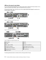
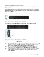
Page 180: ...th dual port HIC Figure 13 DE4000 controller with quad port HIC Figure 14 DE6000 controller with quad port HIC 1 Cache Active 2 Locate 3 Attention 4 Activity 5 Seven segment display 6 HIC Host Port Link Status 7 HIC Host Port Attention 8 SAS Expansion Port Link Status 9 SAS Expansion Port Attention 10 Baseboard Host Port Link Status 11 Baseboard Host Port Attention 12 Ethernet Status 13 Ethernet A...

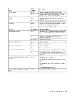
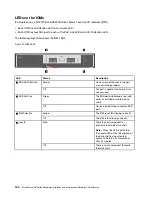
Page 181: ... switch is up Off There is no link between the controller and the connected Ethernet port Blinking green There is Ethernet activity Ethernet Link State left Green Link is established Off No link is established SAS expansion Port Link Green Link is established Off No link is established SAS expansion Port Link Fault Amber Port is degraded one or more Phys in the port is down Off Port is optimal all...

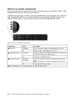
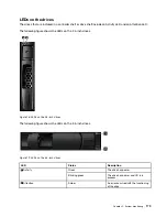
Page 182: ... Components Status Description 1 Power LED Solid green One or more power supplies are delivering power to the shelf Off No power supply is delivering power to the shelf 2 Attention LED front Solid amber There is an error with the function of one or more of the following shelf drives IOMs power supplies or fans Off The system is operating normally 3 Location LED front Solid blue or blinking blue Th...

Page 183: ...rive shelf with 24 drives Figure 17 ODP push button on controller shelf and drive shelf with 24 drives 1 ODP push button Step 1 Press and hold the push button until the first number on the seven segment display starts to blink It might take up to three seconds for the number to blink If the number does not blink in this time release the button and press it again Make sure to press the button all t...

Page 184: ...m 0 to 9 The second number continues to blink Step 5 Lock in the desired number and exit the programming mode by pressing and holding the button until the second number stops blinking It might take up to three seconds for the second number to stop blinking 178 ThinkSystem DE Series Hardware Installation and Maintenance Guide for 2U Enclosures ...

Page 185: ...he 2 5 inch drives Figure 18 LEDs on the 2 5 inch drives The following figure shows the LEDs on the 3 5 inch drives Figure 19 LEDs on the 3 5 inch drives LED Status Description 1 Activity Green The drive has power Blinking green The drive has power and I O is in process 2 Attention Amber An error occurred with the functioning of the drive Chapter 5 System monitoring 179 ...

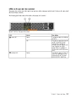
Page 186: ...ror has occurred 2 SAS Port Link Green The SAS port established a link with either a controller or another drive shelf Off No link is established to another SAS port 3 IOM Attention Amber The IOM is not functioning correctly Off The IOM is functioning correctly 4 Locate Blue There is an active request to physically locate the drive shelf Note When this LED is activated the Locate LED on the left e...

Page 187: ...r LED Status Description 1 Power LED Green The power supply is functioning correctly Off The power supply failed the AC switch is turned off the AC power cord is not properly installed or the AC power cord input voltage is not within margin there is a problem at the source end of the AC power cord 2 Attention LED Amber The power supply has a fault or there is no input power to this power canister ...

Page 188: ...ad 3 Diagnostic dot in the upper left Green The seven segment display shows the diagnostic code Off The seven segment display shows the tray ID Seven segment display sequence codes Seven segment display sequences enable you to understand errors and operational states of the various components in your storage array Each sequence shows a two digit category code followed by a two digit detail code Th...

Page 189: ...tic failure dE Lx Lock down codes See Seven segment display lock down codes on page 185 Category delimiter The double hyphen is the separator between category detail code pairs when more than one pair exists in the sequence End of sequence delimiter Blank display turns off at the end of a sequence Seven segment display codes when controller turns on The following table describes the seven segment ...

Page 190: ...he backup OS bb blank The CPU temperature has exceeded the warning level OS OH blank Component failure when the controller is operational Failed host interface card HIC OS CF HX blank Failed flash drive OS CF Fx blank Power on diagnostic failure Failure of a component that is not a field replaceable unit SE dF blank Processor DIMM failure SE dF CF Px blank Cache memory DIMM failure SE dF CF Cx bla...

Page 191: ...he conditions that cause the controller to be in a suspended state Lock down code Description L0 The controller types in a two controller configuration are mismatched L1 Missing interconnect canister L2 A persistent memory error has occurred L3 A persistent hardware error has occurred L4 A persistent data protection error has occurred L5 An auto code synchronization ACS failure has been detected L...

Page 192: ...Storage array alert traps When a critical Major Event Log MEL event is generated the embedded SNMP agent delivers a storage array alert trap to all configured trap destinations This message contains the following data MIB variable field Description Storage array name Storage array user label If the label contains non ASCII characters the resulting variable binding is populated with the fixed strin...

Page 193: ...urs when The logged device generated a PFA condition Event Name Drive PFA Event description Impending drive failure detected by drive Event Group Destination Driver Event Priority CRITICAL_EVENT Log Group Controller 0x1 Event Category Error 0x1 Event Component Type Drive 0x0 0x1 Event Specific Data Optional data is provided with this event MEL_DATA_DRIVE_CDB RecoveryFailureType REC_IMPENDING_DRIVE...

Page 194: ... is not provided with this event RecoveryFailureType REC_DRIVE_INCOMPATIBLE_PI_TYPE driveIncompatiblePIType html MEL_EV_FC_LINK_ERROR_THRESHOLD_CRITICAL 0x1207 This event occurs when A Link Error count exceeds the threshold the first time Event Name Link Error Threshold Critical Event description Fibre channel link errors threshold exceeded Event Group Fibre Channel Source Driver Event Priority CR...

Page 195: ...graded Event Group Fibre Channel Source Driver Event Priority CRITICAL_EVENT Log Group Controller 0x1 Event Category Error 0x1 Event Component Type Channel 0x0 0x6 Event Specific Data Optional data is provided with this event MEL_DATA_DDS_RECORD RecoveryFailureType REC_CHANNEL_DEGRADED degradedDriveChannel html MEL_EV_FC_SFP_FAILED 0x120A This event occurs when The SFP on an XBB class controller h...

Page 196: ...gged when the number of times a controller reboots reaches a certain threshold in a certain time window Event Name Excessive Reboots Detected Event description Excessive reboots exceptions have occurred on the controller Event Group System Event Priority CRITICAL_EVENT Log Group Controller 0x1 Event Category Error 0x1 Event Component Type Controller 0x0 0x8 Event Specific Data Optional data is not...

Page 197: ...Event Priority CRITICAL_EVENT Log Group System 0x0 Event Category Error 0x1 Event Component Type Channel 0x0 0x6 Event Specific Data Optional data is not provided with this event RecoveryFailureType N A MEL_EV_DFC_ESM_MISWIRE 0x1510 This event occurs when Two IOMs ESMs of the same tray are seen on the same channel Event Name ESM Miswire Event description IOM ESM miswire Event Group Fibre Channel s...

Page 198: ...nnel hardware fails Event Name Drive Channel Hardware Failed Event description Drive Channel hardware failed Event Group Fibre Channel specific Destination Driver Event Priority CRITICAL_EVENT Log Group Controller 0x1 Event Category Error 0x1 Event Component Type Channel 0x0 0x6 Event Specific Data Optional data is provided with this event MEL_DATA_DDS_RECORD RecoveryFailureType N A MEL_EV_DFC_LSD...

Page 199: ... ports involved in the miswire Event Name Controller Miswire Event description Controller miswire for drive channel occurred Event Group Fibre Channel specific Destination Driver Event Priority CRITICAL_EVENT Log Group System 0x0 Event Category Error 0x1 Event Component Type Channel Port 0x2 0x3 Event Specific Data Optional data is not provided with this event RecoveryFailureType N A MEL_EV_DFC_MI...

Page 200: ...L_DATA_TRAYNUMBER RecoveryFailureType REC_FIBRE_TRUNK_INCOMPATIBLE_ESM fcTrunkingIncompatibleEsm html MEL_EV_DFC_FIBRE_TRUNK_MISWIRE 0x1525 This event occurs when Drive enclosures are trunk capable but are not cabled correctly for trunking or the cables themselves are missing There should be one MEL event logged irrespective of the number of devices in miswire Event Name Fibre Trunk Miswire Event ...

Page 201: ... event is only logged on SAS 1 controllers Mary Jane and Winterpark Event Name Initiator Overflow Event description SAS source driver partner initiator overflow Event Group SAS Specific Source Driver and Miscellaneous Event Priority CRITICAL_EVENT Log Group Controller 0x1 Event Category Failure 0x2 Event Component Type Controller 0x0 0x8 Event Specific Data Optional data is provided with this even...

Page 202: ...roller 0x0 0x8 Event Specific Data Optional data is not provided with this event RecoveryFailureType N A MEL_EV_DSAS_TOPOLOGY_MISWIRE 0x1700 This event occurs when A RAID controller detects an invalid SAS topology such as an expander PHY with a table routing attribute attached to another expander PHY with a table routing attribute a SAS loop or multiple ports with the same SAS address Event Name D...

Page 203: ...re Event Name DSAS ESM Miswire Event description SAS IOM ESM miswire detected Event Group SAS Specific Destination Driver Event Priority CRITICAL_EVENT Log Group System 0x0 Event Category Error 0x1 Event Component Type Tray Component ESM GBIC SFP Power Supply or Fan 0x0 0x7 Event Specific Data Optional data is not provided with this event RecoveryFailureType REC_SAS_PORT_MISWIRED SASMiswire html R...

Page 204: ...c Destination Driver Event Priority CRITICAL_EVENT Log Group System 0x0 Event Category Error 0x1 Event Component Type Tray Component ESM GBIC SFP Power Supply or Fan 0x0 0x7 Event Specific Data Optional data is provided with this event MEL_SYMBOL_DATA_SLOTNUMBER RecoveryFailureType REC_SAS_PORT_FAILED failedSASPort html MEL_EV_DSAS_EXP_PORT_DEV_MISWIRE 0x170A This event occurs when Information not...

Page 205: ...ort html MEL_EV_DSAS_WPORT_DEG_TO_FAIL_CTLR 0x1710 This event occurs when A device attached to the controller is determined to be present but none of the PHYs that comprise the port attached to that device can connect to or communicate with the device Event Name Controller Wide Port Has Gone To Failed State Event description Controller wide port has gone to failed state Event Group SAS Specific De...

Page 206: ...urs If Zion or Samoa HICS the firmware cannot successfully restart the iSCSI interface Event Name iSCSI Failed Host Card Event description Failed I O host card iSCSI interface error detected Event Group iSCSI Specific Event Priority CRITICAL_EVENT Log Group System 0x0 Event Category Failure 0x2 Event Component Type Host Board 0x2 0x5 Event Specific Data Optional data is not provided with this even...

Page 207: ...ent RecoveryFailureType REC_MISSING_DRIVE_LOCKDOWN missingDrivesLockdown html MEL_EV_HIC_CONFIGURATION_OOC 0x1908 This event occurs when A controller has detected that the combination of host interface cards are out of compliance with limitations of the controller and or the firmware Event Name HIC Configuration OOC Event description A controller has detected that the combination of host interface...

Page 208: ...pted write Event Group VDD Event Priority CRITICAL_EVENT Log Group System 0x0 Event Category Notification 0x4 Event Component Type Controller 0x0 0x8 Event Specific Data Optional data is provided with this event MEL_DATA_LBA_INFO RecoveryFailureType N A MEL_EV_DRIVE_FAIL_READ_ERROR_SCAN_CYCLE 0x203B This event occurs when A drive is failed due to an unrecoverable read error detected during scan cy...

Page 209: ...0 0xD Event Specific Data Optional data is provided with this event MEL_DATA_PARITY_READ_LBA RecoveryFailureType REC_REDUNDANCY_GROUP_NOT_CONSISTENT_DURING_RECONFIG RedundancyGroupInconsistency html MEL_EV_ISOLATION_REDUN_MISMATCH 0x2046 This event occurs when In RAID 6 environments via media scan with redundancy check or when pre read redundancy check is enabled The event is logged when a drive c...

Page 210: ...n Data is altered due to a detected inconsistency in redundancy The data which was within a redundancy group with multiple redundancy e g RAID 6 was isolated recovered and rewritten to the drive Event Name Data Altered to Correct Redundancy Mismatch Event description Data altered to correct redundancy mismatch Event Group VDD Event Priority CRITICAL_EVENT Log Group System 0x0 Event Category Notifi...

Page 211: ...e Data Assurance Analysis Lockdown Mode Entered Event description Controller is in Analysis Lockdown Mode due to excessive Data Assurance errors Event Group Protection Information Event Priority CRITICAL_EVENT Log Group Controller 0x1 Event Category Notification 0x4 Event Component Type Controller 0x0 0x8 Event Specific Data Optional data is not provided with this event RecoveryFailureType REC_PI_...

Page 212: ...fic Data Optional data is provided with this event MEL_DATA_SMART_BATTERY RecoveryFailureType REC_FAILED_BATTERY failedBattery html MEL_EV_CACHE_DATA_LOSS 0x210E This event occurs when Logged by cache manager when cache blocks can t be successfully recovered Companion to an ASC ASCQ status of 0x0C 0x81 Event Name Cache Data Loss Event description Controller cache memory recovery failed after power...

Page 213: ...ERY_WARN 0x2113 This event occurs when A cache battery is within the specified number of weeks of failing The ASC ASCQ value of 0x3F 0xD9 is also logged with this event Event Name Cache Battery Warning Event description Controller cache battery nearing expiration Event Group Cache Manager Event Priority CRITICAL_EVENT Log Group System 0x0 Event Category Error 0x1 Event Component Type Battery Pack ...

Page 214: ...y Error 0x1 Event Component Type Controller 0x0 0x8 Event Specific Data Optional data is not provided with this event RecoveryFailureType REC_UNSUPPORTED_CACHE_MEMORY_SIZE unsupportedCacheMemSize html MEL_EV_CACHE_BACKUP_INSUFFICIENT_CAPACITY 0x211F This event occurs when The cache backup device is missing leaving insufficient capacity to perform full cache backup Event Name Insufficient Backup De...

Page 215: ...TOO_SMALL_FOR_CACHE MEL_EV_DEDICATED_MIRROR_CHANNEL_FAILED 0x2124 This event occurs when Information not available Event Name Dedicated Mirror Channel Failed Event description Dedicated mirror channel failed Event Group Cache Manager Event Priority CRITICAL_EVENT Log Group Controller 0x1 Event Category Failure 0x2 Event Component Type Controller 0x0 0x8 Event Specific Data Optional data is not pro...

Page 216: ...ICAL_EVENT Log Group Controller 0x1 Event Category Failure 0x2 Event Component Type Controller 0x0 0x8 Event Specific Data Optional data is provided with this event MEL_DATA_INC_BACKUP_REASON RecoveryFailureType N A MEL_EV_WB_CACHING_FORCIBLY_DISABLED 0x212B This event occurs when Write back caching is forcibly disabled beyond a threshold period of time for volumes that are configured to use the w...

Page 217: ...A_LOSS cache_failed_data_loss html MEL_EV_CACHE_NOT_FLUSHED_ON_ONLY_CTLR 0x2131 This event occurs when Logged when the alternate controller is held in reset and this controller fails to flush dirty cache data on failed volume s possibly due to offlined drives The controller should not be replaced to avoid loss of data Event Name Dirty Cache Not Flushed On The Only Active Controller Event descripti...

Page 218: ...acement is too small Event Group Configuration Manager Event Priority CRITICAL_EVENT Log Group System 0x0 Event Category Notification 0x4 Event Component Type Drive 0x0 0x1 Event Specific Data Optional data is provided with this event MEL_DATA_DRV_REPLACE RecoveryFailureType N A MEL_EV_WRONG_SECTOR_SIZE 0x224A This event occurs when A configuration manager posts an UA AEN of ASC ASCQ 0x3F 0x8C ind...

Page 219: ...ta is not provided with this event RecoveryFailureType N A MEL_EV_DRV_NO_RESPONSE 0x224D This event occurs when A configuration manager posts an UA AEN of ASC ASCQ 0x3F 0x85 indicating the controller set the drive state to Failed No Response Event Name Drive No Response Event description Drive failed no response at start of day Event Group Configuration Manager Event Priority CRITICAL_EVENT Log Gr...

Page 220: ...Volume failure Event Group Configuration Manager Event Priority CRITICAL_EVENT Log Group System 0x0 Event Category Failure 0x2 Event Component Type Volume 0x0 0xD Event Specific Data Optional data is not provided with this event RecoveryFailureType REC_FAILED_VOLUME failedVolume html MEL_EV_CFG_READ_FAIL 0x2251 This event occurs when A configuration manager posts an UA AEN of ASC ASCQ 0x3F 0x8E in...

Page 221: ...EVENT Log Group System 0x0 Event Category Notification 0x4 Event Component Type Drive 0x0 0x1 Event Specific Data Optional data is provided with this event MEL_DATA_VOL_LABEL RecoveryFailureType N A MEL_EV_UNCERTIFIED_DRIVE 0x2260 This event occurs when An uncertified drive has been detected in the array Event Name Uncertified Drive Event description Uncertified Drive Detected Event Group Configur...

Page 222: ...ring a reconfiguration operation causing the failure of all volumes in the volume group Event Name Reconfiguration Failed Event description Volume modification operation failed Event Group Configuration Manager Event Priority CRITICAL_EVENT Log Group System 0x0 Event Category Failure 0x2 Event Component Type Volume Group 0x0 0xE Disk Pool 0x3 0x2 Event Specific Data Optional data is provided with ...

Page 223: ...ultipleConfDBs html REC_ NATIVE_VG_FOREIGN_DRIVE_MUTUAL_REF pvgNatVgFrnDrvMutualRef html REC_REPLACED_DRIVE_ WRONG_TYPE incorrectDriveType html REC_VG_CLONED pvgVgCloned html REC_VG_DRIVE_ PART_OF_MULTIPLE_VGS pvgMultVgsRefFrnDrv1 html REC_VG_HAS_DRIVE_PART_OF_MULTIPLE_ VGS pvgMultVgsRefFrnDrv2 html REC_DRIVE_UNSUPPORTED_PROTOCOL_CONNECTION SATA_ unsupported_protocol html REC_DRIVE_INCOMPATIBLE_PI...

Page 224: ...removed Event Group Configuration Manager Event Priority CRITICAL_EVENT Log Group Drive 0x2 Event Category Failure 0x2 Event Component Type Drive 0x0 0x1 Event Specific Data Optional data is not provided with this event RecoveryFailureType REC_HOTSPARE_DRIVE_MISSING missingHotSpare html MEL_EV_SSD_AT_END_OF_LIFE 0x226E This event occurs when It is recommended that the customer schedule replacing t...

Page 225: ...th this event RecoveryFailureType REC_DRIVE_UNSUPPORTED_CAPACITY driveUnsupportedDriveCap html MEL_EV_HOT_SPARE_IN_USE 0x2273 This event occurs when Information not available Event Name Hot Spare In Use Event description Hot spare in use Event Group Configuration Manager Event Priority CRITICAL_EVENT Log Group System 0x0 Event Category Notification 0x4 Event Component Type Drive 0x0 0x1 Event Spec...

Page 226: ...CAL_EVENT Log Group System 0x0 Event Category Notification 0x4 Event Component Type Volume Group 0x0 0xE Disk Pool 0x3 0x2 Event Specific Data Optional data is not provided with this event RecoveryFailureType REC_VOLUME_GROUP_INCOMPLETE incompleteVGorDP html MEL_EV_DRIVE_UNSUP_INTERPOSER_FW_VER 0x2276 This event occurs when The firmware version in an interposer is incompatible with the drive behin...

Page 227: ...0x0 0x1 Event Specific Data Optional data is provided with this event MEL_DATA_NON_ZERO_LOWEST_ALIGNED_LBA RecoveryFailureType REC_DRIVE_INCOMPATIBLE_ALIGNMENT_FOR_EMULATION_DRIVE incompatibleDriveAlignment html MEL_EV_COPY_THEN_FAIL_NO_SPARE 0x227C This event occurs when The controller detects an impending drive failure but is unable to trigger an automatic drive copy operation because there is n...

Page 228: ...domain name of the NTP server using the administered primary or secondary DNS Event Name Primary Secondary NTP Server Domain Name Resolution Failure Event description A NTP domain server name is either invalid or the configured primary or secondary DNS servers are unreachable Event Group Configuration Manager Event Priority CRITICAL_EVENT Log Group System 0x0 Event Category Notification 0x4 Event ...

Page 229: ...he network Event Group Configuration Manager Event Priority CRITICAL_EVENT Log Group System 0x0 Event Category Notification 0x4 Event Component Type Controller 0x0 0x8 Event Specific Data Optional data is not provided with this event RecoveryFailureType REC_NET_NTP_SERVICE_UNAVAILABLE ntpServiceUnavailable html MEL_EV_SBB_VALIDATION_FAIL_FOR_POWER_SUPPLY 0x2302 This event occurs when A power suppl...

Page 230: ...mismatched_midplane_eeproms html MEL_EV_SBB_TWO_WIRE_INTERFACE_BUS_FAILURE 0x2304 This event occurs when A failure is detected on the two wire interface bus Event Name Two Wire Interface Bus Failure Event description Two wire interface bus failure Event Group SBB Validation Event Priority CRITICAL_EVENT Log Group System 0x0 Event Category Error 0x1 Event Component Type Enclosure 0x0 0xA Event Spec...

Page 231: ...nt Group Hot Swap Event Priority CRITICAL_EVENT Log Group System 0x0 Event Category Notification 0x4 Event Component Type Controller 0x0 0x8 Event Specific Data Optional data is not provided with this event RecoveryFailureType REC_REMOVED_CONTROLLER removedCtrl html MEL_EV_ACS_ERROR 0x2602 This event occurs when An auto code synchronization failed Event Name ACS Error Event description Automatic c...

Page 232: ...is event occurs when An inconsistent array lock key situation is detected Event Name FDE Inconsistent Array Lock Key Event description Inconsistent security FDE storage array lock key Event Group Start of Day Event Priority CRITICAL_EVENT Log Group System 0x0 Event Category Failure 0x2 Event Component Type Controller 0x0 0x8 Event Specific Data Optional data is not provided with this event Recover...

Page 233: ...onent Type Battery Pack 0x0 0x9 Event Specific Data Optional data is not provided with this event RecoveryFailureType REC_UPS_ON_BATTERY lostACPower html MEL_EV_UPS_BATTERY_2MIN 0x2803 This event occurs when A UPS battery has transitioned and given the 2 minute warning The UPS has signaled that it has 2 minutes of power left before failing The controllers will flush any dirty data in their caches ...

Page 234: ...subsystem line has transitioned to the Failed state Event Name Line Failed Event description Controller tray component failed Event Group Sub System Monitor Event Priority CRITICAL_EVENT Log Group System 0x0 Event Category Notification 0x4 Event Component Type Enclosure 0x0 0xA Event Specific Data Optional data is provided with this event MEL_SYMBOL_DATA_SLOTNUMBER RecoveryFailureType REC_FAILED_I...

Page 235: ...licate IDs across drive trays Event Group Sub System Monitor Event Priority CRITICAL_EVENT Log Group System 0x0 Event Category Notification 0x4 Event Component Type Tray Component ESM GBIC SFP Power Supply or Fan 0x0 0x7 Event Specific Data Optional data is provided with this event MEL_SYMBOL_DATA_TRAYNUMBER RecoveryFailureType REC_TRAYID_CONFLICT trayIdConflict html MEL_EV_TEMP_SENSOR_WARNING 0x2...

Page 236: ...occurs when A controller detects that a temperature sensor is missing This event is logged in the temp sensor is missing which means an SES in an enclosure is missing The user should check the enclosure to make sure both SES components are installed A different event is A temp sensor is present but failed Event Name Temperature Sensor Missing Event description Temperature sensor removed Event Grou...

Page 237: ...passed on both ports Event Name Bypass Generic Event description Drive by passed Event Group Sub System Monitor Event Priority CRITICAL_EVENT Log Group System 0x0 Event Category Failure 0x2 Event Component Type Drive 0x0 0x1 Event Specific Data Optional data is provided with this event MEL_SYMBOL_DATA_TRAYNUMBER RecoveryFailureType REC_DRIVE_BYPASSED_CAUSE_UNKNOWN bypassedDrive html MEL_EV_CONT_RE...

Page 238: ...OL_DATA_TRAYNUMBER RecoveryFailureType REC_LOST_REDUNDANCY_TRAY noRedundancyTray html MEL_EV_DRIVE_REDUNDANCY_LOSS 0x282D This event occurs when An array determines that a loss of drive path redundancy is a persistent condition Event Name Drive Redundancy Loss Event description Drive path redundancy lost Event Group Sub System Monitor Event Priority CRITICAL_EVENT Log Group System 0x0 Event Catego...

Page 239: ...ALLOWED 0x2830 This event occurs when Logged for two reasons 1 when mixed drive types are not supported and 2 when firmware determines that a mixture of physical drive types is present Mixed Drive Types is configured as a premium feature and MDT has not been enabled Event Name Mixed Drive Types Not Allowed Event description Mixed drive types out of compliance Event Group Sub System Monitor Event P...

Page 240: ..._EVENT Log Group System 0x0 Event Category Notification 0x4 Event Component Type Enclosure 0x0 0xA Event Specific Data Optional data is provided with this event MEL_SYMBOL_DATA_TRAYNUMBER RecoveryFailureType REC_UNSUPPORTED_TRAY unsupportedDriveTray html MEL_EV_CONT_ID_MISMATCH 0x2833 This event occurs when Either the base controller or the host interface card is found to be different between the ...

Page 241: ...overyFailureType REC_DRIVE_TRAYS_NOT_GROUPED_TOGETHER driveTrayCluster html MEL_EV_DISCRETE_LINE_FAIL 0x2836 This event occurs when A discrete line test has failed due to either a fault Controller or a faulty Interconnect Module Event Name Discrete Line Failure Event description Discrete lines diagnostic failure Event Group Sub System Monitor Event Priority CRITICAL_EVENT Log Group System 0x0 Even...

Page 242: ...or Event Priority CRITICAL_EVENT Log Group System 0x0 Event Category Notification 0x4 Event Component Type Power Supply 0x0 0x2 Event Specific Data Optional data is provided with this event MEL_SYMBOL_DATA_SLOTNUMBER RecoveryFailureType REC_FAILED_POWER_SUPPLY failedPowerSupply html MEL_EV_CONT_SUBMODEL_MISMATCH 0x2841 This event occurs when An alternate controller has performed a self lockdown du...

Page 243: ..._DATA_TRAYNUMBER RecoveryFailureType REC_ESM_HARDWARE_MISMATCH ESMHwMismatch html MEL_EV_LINK_SPEED_SWITCH_CHANGE 0x284B This event occurs when A controller detects that an ESM hardware mismatch condition has been cleared Event Name Link Speed Switch Change Event description Link Speed data rate switch position has changed Event Group Sub System Monitor Event Priority CRITICAL_EVENT Log Group Syst...

Page 244: ...igured tray Event Group Sub System Monitor Event Priority CRITICAL_EVENT Log Group System 0x0 Event Category Notification 0x4 Event Component Type Enclosure 0x0 0xA Event Specific Data Optional data is provided with this event MEL_SYMBOL_DATA_TRAYNUMBER RecoveryFailureType REC_ENCLOSURE_MISCONFIGURED misconfiguredTray html MEL_EV_FACTORY_DEFAULT_MISMATCH 0x2852 This event occurs when Two IOMs ESMs...

Page 245: ...Category Failure 0x2 Event Component Type Drive 0x0 0x1 Event Specific Data Optional data is provided with this event MEL_DATA_DRIVE_FAULT RecoveryFailureType REC_DRIVE_BYPASSED_SINGLE_PORT bypassedDrive html MEL_EV_CONT_ID_READ_FAILURE 0x2855 This event occurs when An alternate controller board ID cannot be read Event Name Alternate Board Controller ID Cannot Be Read Event description Controller ...

Page 246: ...en opened or removed Event Name Drawer Open Or Removed Event description Drawer open or removed Event Group Sub System Monitor Event Priority CRITICAL_EVENT Log Group System 0x0 Event Category Notification 0x4 Event Component Type Drawer 0x3 0x0 Event Specific Data Optional data is provided with this event MEL_SYMBOL_DATA_SLOTNUMBER RecoveryFailureType REC_DRAWER_OPENED missingDrawer html MEL_EV_E...

Page 247: ...ray has become degraded Event Group Sub System Monitor Event Priority CRITICAL_EVENT Log Group System 0x0 Event Category Notification 0x4 Event Component Type Drawer 0x3 0x0 Event Specific Data Optional data is provided with this event MEL_DCMM_DRAWER_PATH_FAIL RecoveryFailureType REC_DRAWER_DEGRADED degradedDrawer html MEL_EV_DRAWER_INVALID 0x2861 This event occurs when An invalid drawer has been...

Page 248: ...e SFP has failed It could be failed because it is the wrong type for the protocol in use Event Name Host SFP Removed Event description Host side SFP failed Event Group Sub System Monitor Event Priority CRITICAL_EVENT Log Group System 0x0 Event Category Notification 0x4 Event Component Type Controller SFP 0x2 0x8 Event Specific Data Optional data is not provided with this event RecoveryFailureType ...

Page 249: ... the invalid configuration state Event Name Entering Invalid System Configuration Event description Entering invalid system configuration Event Group ICM Event Priority CRITICAL_EVENT Log Group System 0x0 Event Category Notification 0x4 Event Component Type Controller 0x0 0x8 Event Specific Data Optional data is not provided with this event RecoveryFailureType N A MEL_EV_FLASH_CACHE_FAILED_CACHE_S...

Page 250: ...uction reserved disk count value This occurs when failed drives are rebuilt and use reserved space Event Name Disk Pool Reconstruction Reserved Drive Count Below Threshold Event description Disk pool reconstruction reserved drive count is below threshold Event Group Disk Pool Event Priority CRITICAL_EVENT Log Group System 0x0 Event Category Failure 0x2 Event Component Type Disk Pool 0x3 0x2 Event ...

Page 251: ...ol Event Priority CRITICAL_EVENT Log Group System 0x0 Event Category Failure 0x2 Event Component Type Disk Pool 0x3 0x2 Event Specific Data Optional data is not provided with this event RecoveryFailureType REC_DISK_POOL_UTILIZATION_CRITICAL diskPoolCapacityCritical html MEL_EV_DISK_POOL_CAPACITY_DEPLETED 0x3809 This event occurs when A disk pool has completely run out of capacity This is typically...

Page 252: ...lInsuffMemory html MEL_EV_DISK_POOL_CORRUPTED_DB_RECORD 0x380D This event occurs when A disk pool corrupts database record Event Name Disk Pool Corrupted DB Record Event description Disk pool has corrupted database record Event Group Disk Pool Event Priority CRITICAL_EVENT Log Group System 0x0 Event Category Failure 0x2 Event Component Type Controller 0x0 0x8 Event Specific Data Optional data is n...

Page 253: ...og Group System 0x0 Event Category Command 0x3 Event Component Type Controller 0x0 0x8 Event Specific Data Optional data is provided with this event MEL_SYMBOL_DATA_CONTROLLER_NUMBER RecoveryFailureType N A MEL_EV_SYMBOL_AUTH_FAIL_CONT_LOCKOUT 0x5038 This event occurs when A lockout state has been entered Event Name SYMbol Auth Fail Cont Lockout Event description Storage array 10 minute lockout ma...

Page 254: ... the threshold Event Name Lock Key Failed Validation Attempts Exceeded Event description Security FDE key failed validation attempts due to excessive tries Event Group SYMbol Server Event Priority CRITICAL_EVENT Log Group System 0x0 Event Category Command 0x3 Event Component Type Controller 0x0 0x8 Event Specific Data Optional data is not provided with this event RecoveryFailureType REC_SECURITY_K...

Page 255: ...ler Failed Event description Base controller diagnostic on alternate controller failed Event Group Base Controller Diagnostic Event Priority CRITICAL_EVENT Log Group Controller 0x1 Event Category Failure 0x2 Event Component Type Controller 0x0 0x8 Event Specific Data Optional data is not provided with this event RecoveryFailureType REC_IOC_DIAG_FAIL ctrlIocDiagFailed html MEL_EV_IOC_FAILURE 0x5102...

Page 256: ... Optional data is provided with this event MEL_DATA_SASFI_PHY_ERROR_BCAST RecoveryFailureType N A MEL_EV_SAS_PHY_DISABLED_BYPASSED_DRIVE 0x5104 This event occurs when A PHY that is connected to a drive is disabled The error could be in the expander or drive This event is generated only when the controller disables a PHY not the ESM The easiest replacement option is the drive so it should be called...

Page 257: ...x5106 This event occurs when A bad SAS PHY has disabled a shared wide port Event Name SAS PHY Disabled Shared Wide Port Event description SAS PHY disabled shared wide port Event Group Base Controller Diagnostic Event Priority CRITICAL_EVENT Log Group Controller 0x1 Event Category Failure 0x2 Event Component Type Channel 0x0 0x6 Event Specific Data Optional data is provided with this event MEL_DATA...

Page 258: ...ion 0x4 Event Component Type Relative 0x0 0x0 Event Specific Data Optional data is provided with this event MEL_SPM_DATA_NOTIFY_INVALID_OSINDEX RecoveryFailureType REC_INVALID_HOST_TYPE_INDEX invalidHostType html MEL_EV_INACTIVE_HOST_PORT_REGISTERED 0x5224 This event occurs when A Host Context Agent HCA attempted to register a host port associated with a host that already has storage partition map...

Page 259: ... Event Priority CRITICAL_EVENT Log Group System 0x0 Event Category Notification 0x4 Event Component Type iSCSI Initiator 0x2 0x9 Event Specific Data Optional data is provided with this event MEL_SPM_DATA_HCA_REGISTRATION RecoveryFailureType REC_INACTIVE_INITIATOR inactiveHostIdentifier html MEL_EV_SAFE_NON_COMPLIANCE 0x5402 This event occurs when There are features enabled that have not been purch...

Page 260: ... When this condition is detected both controllers are treated as though they are subject to the restrictions Event Name Mismatched Gold Key Settings Event description Gold Key mismatched settings Event Group SAFE Event Priority CRITICAL_EVENT Log Group System 0x0 Event Category Notification 0x4 Event Component Type Relative 0x0 0x0 Event Specific Data Optional data is not provided with this event ...

Page 261: ...E Event Priority CRITICAL_EVENT Log Group Controller 0x1 Event Category Notification 0x4 Event Component Type Relative 0x0 0x0 Event Specific Data Optional data is provided with this event MEL_DATA_EVAL_MEL_DATA RecoveryFailureType REC_EVALUATION_LICENSE_EXPIRATION_IMMINENT featureTrialNearExpiration html MEL_EV_DIAG_READ_FAILURE 0x560D This event occurs when Runtime Diagnostics Read test failed o...

Page 262: ...URE 0x560F This event occurs when Runtime Diagnostics Write test failed on this controller Event Name Runtime Diagnostics error Diagnostic write test failed Event description Diagnostics write test failed on controller Event Group Runtime Diagnostics Event Priority CRITICAL_EVENT Log Group System 0x0 Event Category Failure 0x2 Event Component Type Controller 0x0 0x8 Event Specific Data Optional da...

Page 263: ...VENT Log Group System 0x0 Event Category Failure 0x2 Event Component Type Controller 0x0 0x8 Event Specific Data Optional data is not provided with this event RecoveryFailureType N A MEL_EV_DIAG_CONFIG_ERR_ALT 0x5617 This event occurs when A configuration error of the alternate controller occurs for running diagnostics Event Name Runtime Diagnostics error Alternate controller configuration error E...

Page 264: ...CK_ALTCTL_NOT_FUNC 0x6107 This event occurs when A controller s alternate is non functional and is being held in reset Event Name DBM Hck Altctl Not Func Event description This controller s alternate is non functional and is being held in reset Event Group Hierarchical Config DB Event Priority CRITICAL_EVENT Log Group System 0x0 Event Category Failure 0x2 Event Component Type Controller 0x0 0x8 Ev...

Page 265: ...ent Name Mirror Dual Primary Event description Dual primary volume conflict Event Group Mirroring Event Priority CRITICAL_EVENT Log Group System 0x0 Event Category Notification 0x4 Event Component Type Volume 0x0 0xD Event Specific Data Optional data is not provided with this event RecoveryFailureType REC_MIRROR_DUAL_PRIMARY mirrorDualPrimary html MEL_EV_MIRROR_DUAL_SECONDARY 0x6401 This event occ...

Page 266: ...a Optional data is not provided with this event RecoveryFailureType REC_MIRROR_UNSYNCHRONIZED mirrorUnsync html MEL_EV_RVM_WRITE_MODE_INCONSISTENT 0x6411 This event occurs when The mirror relationship has inconsistent write mode Event Name RVM Write Mode Inconsistent Event description Mirror relationship has inconsistent write mode Event Group Mirroring Event Priority CRITICAL_EVENT Log Group Syst...

Page 267: ...e RMTVOL Node WWN Changed Failed Event description Failed to communicate storage array s world wide name Event Group Remote Volume Event Priority CRITICAL_EVENT Log Group System 0x0 Event Category Failure 0x2 Event Component Type Volume 0x0 0xD Event Specific Data Optional data is provided with this event MEL_DATA_RMTVOL_NODE_WWN_CHANGED RecoveryFailureType REC_REMOTE_WWN_CHANGE_FAILED wwnChangeFa...

Page 268: ...e 0x0 0xD Event Specific Data Optional data is provided with this event MEL_DATA_USM_UNREADABLE_SECTOR RecoveryFailureType REC_USM_UNREADABLE_SECTORS_EXIST UnreadableSctrs html MEL_EV_USM_DATABASE_FULL 0x6703 This event occurs when A database is full Event Name USM Database Full Event description Overflow in unreadable sector database Event Group Unreadable Sector Management Event Priority CRITICA...

Page 269: ...roller detects that a wrong password or corrupted password has been entered This event is a security measure and does not cause a Needs Attention condition on the array Event Name SPRI Wrong Password Event description Support Recovery Interface SPRI wrong password Event Group Support and Recovery Interface Event Priority CRITICAL_EVENT Log Group Controller 0x1 Event Category Notification 0x4 Event...

Page 270: ...agement Event Priority CRITICAL_EVENT Log Group Controller 0x1 Event Category Error 0x1 Event Component Type Controller 0x0 0x8 Event Specific Data Optional data is not provided with this event RecoveryFailureType REC_FEATURE_NOT_COMPLIANT nonCompliantFeature html MEL_EV_BBU_OVERHEATED 0x7300 This event occurs when The BBU is overheated Event Name BBU Overheated Event description Battery backup un...

Page 271: ...th this event MEL_DATA_SMART_BATTERY RecoveryFailureType REC_BATTERY_WARN batteryReplacementRequired html MEL_EV_BATTERY_MISSING 0x7306 This event occurs when Information not available Event Name Battery Missing Event description Battery missing Event Group Battery Manager Event Priority CRITICAL_EVENT Log Group System 0x0 Event Category Notification 0x4 Event Component Type Battery Pack 0x0 0x9 E...

Page 272: ...Controller 0x1 Event Category Failure 0x2 Event Component Type Cache Backup Device 0x2 0xC Event Specific Data Optional data is not provided with this event RecoveryFailureType REC_CACHE_BACKUP_DEVICE_FAILED failedCacheBackupDev html MEL_EV_CACHE_BACKUP_DEV_WRITE_PROTECTED 0x7501 This event occurs when Write protection is enabled on the cache backup device Event Name Cache Backup Device Write Prot...

Page 273: ...is event RecoveryFailureType N A MEL_EV_PIT_ROLLBACK_PAUSED 0x7800 This event occurs when A PiT rollback operation has been paused Event Name PiT Rollback Paused Event description Snapshot image rollback paused Event Group Pit Group Support Event Priority CRITICAL_EVENT Log Group System 0x0 Event Category Notification 0x4 Event Component Type Snapshot Image 0x3 0x3 Event Specific Data Optional dat...

Page 274: ...Category Notification 0x4 Event Component Type Volume 0x0 0xD Consistency Group 0x3 0x5 Event Specific Data Optional data is not provided with this event RecoveryFailureType REC_PIT_GROUP_FAILED failedPgCgMember html MEL_EV_VIEW_REPOSITORY_FULL 0x7805 This event occurs when The view repository is full the current allocation has been consumed Event Name View Repository Full Event description Snapsh...

Page 275: ...EC_PIT_VIEW_FAILED failedPiTVolume html MEL_EV_PIT_PURGED 0x7807 This event occurs when A PiT has been purged Event Name PiT Purged Event description Snapshot image purged Event Group Pit Group Support Event Priority CRITICAL_EVENT Log Group System 0x0 Event Category Notification 0x4 Event Component Type Snapshot Image 0x3 0x3 Event Specific Data Optional data is provided with this event MEL_DATA_...

Page 276: ...lume 0x0 0xD Event Specific Data Optional data is provided with this event MEL_DATA_VOL_LABEL RecoveryFailureType REC_TPV_FAILED failedThinVolume html MEL_EV_ARVM_AMG_INTERNAL_SUSPENSION 0x7C02 This event occurs when A controller firmware internally suspends synchronization for an AMG This usually is the result of an error condition that requires user intervention to resolve Event Name Async Mirro...

Page 277: ...T amgRoleConflict html MEL_EV_ARVM_AMG_RECOVERY_POINT_LOST 0x7C04 This event occurs when An AMG s recovery point is lost Event Name Async Mirror Group Recovery Point Lost Event description A recovery point for an asynchronous mirror group was lost Event Group ARVM Event Priority CRITICAL_EVENT Log Group System 0x0 Event Category Failure 0x2 Event Component Type Asynchronous Mirror Group 0x3 0x7 Ev...

Page 278: ...p secondary member repository is full Event Group ARVM Event Priority CRITICAL_EVENT Log Group System 0x0 Event Category Notification 0x4 Event Component Type Volume 0x0 0xD Event Specific Data Optional data is provided with this event MEL_DATA_AMG_MEMBER_REF RecoveryFailureType REC_ARVM_SECONDARY_REPOSITORY_FULL mirrorReposFullSecondary html MEL_EV_ARVM_AMG_SYNC_PAUSED_ALT_STATE 0x7C34 This event...

Page 279: ..._EVENT Log Group System 0x0 Event Category Notification 0x4 Event Component Type Asynchronous Mirror Group 0x3 0x7 Event Specific Data Optional data is provided with this event MEL_DATA_AMG_REF RecoveryFailureType REC_ARVM_ROLE_CHANGE_PAUSED remoteNoArray html MEL_EV_SCT_COMMAND_UNSUPPORTED 0x7D00 This event occurs when Logged by MEL event VDM Event Name SCT Commands Unsupported Event description ...

Page 280: ...ates a missing out of date or misconfigured multipath driver installed on the host or an incorrect host type specified for this host in the array configuration Event Name Multipath Configuration Error Event description Host multipath driver configuration error detected Event Group AutoLoadBalancing Event Priority CRITICAL_EVENT Log Group System 0x0 Event Category Error 0x1 Event Component Type Hos...

Page 281: ...oller is unable to communicate with the configured Directory Services server Event Name Directory Services Server Configuration Error Event description A Directory Services server is unreachable or misconfigured Event Group Security Events Event Priority CRITICAL_EVENT Log Group System 0x0 Event Category Error 0x1 Event Component Type Enclosure 0x0 0xA Event Specific Data Optional data is provided...

Page 282: ...276 ThinkSystem DE Series Hardware Installation and Maintenance Guide for 2U Enclosures ...

Page 283: ...ces services and support Warranty information https support lenovo com warranty Provides product warranty information Features On Demand https fod lenovo com Provides license information for Features On Demand FoD You can obtain and activate your FoD key file Support telephone list https datacentersupport lenovo com contactus Provides access to worldwide support phone list Lenovo Community https c...

Page 284: ...278 ThinkSystem DE Series Hardware Installation and Maintenance Guide for 2U Enclosures ...

Page 285: ...n new editions of the publication Lenovo may make improvements and or changes in the product s and or the program s described in this publication at any time without notice The products described in this document are not intended for use in implantation or other life support applications where malfunction may result in injury or death to persons The information contained in this document does not ...

Page 286: ...eded its maximum guaranteed number of program erase cycles as documented in the Official Published Specifications for the device Lenovo makes no representations or warranties with respect to non Lenovo products Support if any for the non Lenovo products is provided by the third party not Lenovo Some software might differ from its retail version if available and might not include user manuals or al...

Page 287: ...ficiency by Particle Size Atlanta American Society of Heating Refrigerating and Air Conditioning Engineers Inc 2 The deliquescent relative humidity of particulate contamination is the relative humidity at which the dust absorbs enough water to become wet and promote ionic conduction 3 ANSI ISA 71 04 1985 Environmental conditions for process measurement and control systems Airborne contaminants Ins...

Page 288: ...RoHS declaration Taiwan import and export contact information Contacts are available for Taiwan import and export information 282 ThinkSystem DE Series Hardware Installation and Maintenance Guide for 2U Enclosures ...

Page 289: ...00 DE6000 replacing batteries 91 drive firmware downloading files 169 upgrade considerations 164 upgrade procedure 169 upgrade workflow 165 upgrading 170 drives 12 or 24 drive shelf ESD and handling requirements 117 numbering scheme of drives 116 overview of drive replacement procedure 116 replacement preparation 118 replacing drives in shelf 118 F Feature Code 152 Feature Enable Identifier 152 fe...

Page 290: ...aiwan import and export contact information 282 telecommunication regulatory statement 281 trademarks 280 U upgrades controller software and firmware 166 drive firmware 169 host interface card preparation 130 host interface card upgrade procedure 130 V VMware host configuration configuring array side iSCSI networking 57 configuring FC switches 54 configuring host side iSCSI networking 59 configuri...

Page 291: ......

Page 292: ......
Reviews: