Note:
If the computer enters the hibernation mode while it is docked to the docking station, do not undock it
before resuming normal operation. If you do undock it and then try to resume normal operation, you will get
an error message, and you will have to restart the system.
If you have defined one of the following actions as the event that causes the system to go into hibernation
mode, perform that action.
• Closing the lid.
• Pressing the power button.
Also, the computer goes into hibernation mode automatically after a period of inactivity specified in power
plan settings.
When the power is turned on, the computer returns from hibernation mode and resumes operation. The
hibernation file in the boot record on the hard disk drive is read, and system status is restored from the hard
disk drive.
Symptom-to-FRU index
This section contains following information:
• “Numeric error codes” on page 38
• “Error messages” on page 39
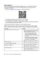
• “Beep symptoms” on page 40
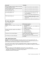
• “No-beep symptoms” on page 41
• “LCD-related symptoms” on page 41
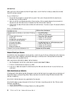
• “Intermittent problems” on page 42
• “Undetermined problems” on page 42
The symptom-to-FRU index in this section lists symptoms and errors and their possible causes. The most
likely cause is listed first, in boldface type.
Note:
Do the FRU replacement or other actions in the sequence shown in the column headed “FRU or
action, in sequence.” If replacing a FRU does not solve the problem, put the original part back in the
computer. Do not replace a nondefective FRU.
This index can also help you determine, during regular servicing, what FRUs are likely to need to be replaced
next.
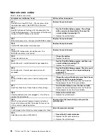
A numeric error is displayed for each error detected in POST or system operation. In the displays,
n
can be
any number.
If no numeric code is displayed, check the narrative descriptions of symptoms. If the symptom is not
described there, go to “Intermittent problems” on page 42.
Note:
For a device not supported by diagnostic codes in the ThinkPad notebook computers, see the manual
for that device.
37
Summary of Contents for 20S7S02U00
Page 1: ...T15 Gen 1 and P15s Gen 1 Hardware Maintenance Manual ...
Page 6: ...iv T15 Gen 1 and P15s Gen 1 Hardware Maintenance Manual ...
Page 11: ...DANGER DANGER DANGER DANGER DANGER Chapter 1 Safety information 5 ...
Page 12: ...6 T15 Gen 1 and P15s Gen 1 Hardware Maintenance Manual ...
Page 13: ...PERIGO PERIGO Chapter 1 Safety information 7 ...
Page 14: ...PERIGO PERIGO PERIGO PERIGO PERIGO 8 T15 Gen 1 and P15s Gen 1 Hardware Maintenance Manual ...
Page 15: ...PERIGO DANGER DANGER DANGER DANGER Chapter 1 Safety information 9 ...
Page 16: ...DANGER DANGER DANGER DANGER VORSICHT 10 T15 Gen 1 and P15s Gen 1 Hardware Maintenance Manual ...
Page 17: ...VORSICHT VORSICHT VORSICHT VORSICHT Chapter 1 Safety information 11 ...
Page 18: ...VORSICHT VORSICHT VORSICHT 12 T15 Gen 1 and P15s Gen 1 Hardware Maintenance Manual ...
Page 19: ...Chapter 1 Safety information 13 ...
Page 20: ...14 T15 Gen 1 and P15s Gen 1 Hardware Maintenance Manual ...
Page 21: ...Chapter 1 Safety information 15 ...
Page 22: ...16 T15 Gen 1 and P15s Gen 1 Hardware Maintenance Manual ...
Page 23: ...Chapter 1 Safety information 17 ...
Page 24: ...18 T15 Gen 1 and P15s Gen 1 Hardware Maintenance Manual ...
Page 25: ...Chapter 1 Safety information 19 ...
Page 26: ...20 T15 Gen 1 and P15s Gen 1 Hardware Maintenance Manual ...
Page 30: ...24 T15 Gen 1 and P15s Gen 1 Hardware Maintenance Manual ...
Page 50: ...44 T15 Gen 1 and P15s Gen 1 Hardware Maintenance Manual ...
Page 73: ...a b c d Chapter 8 Removing or replacing a FRU 67 ...
Page 106: ...100 T15 Gen 1 and P15s Gen 1 Hardware Maintenance Manual ...
Page 109: ......
Page 110: ...Part Number SP40W87587 Printed in 1P P N SP40W87587 ...
Page 111: ... 1PSP40W87587 ...


