


Before servicing the computer
Carefully read this topic before servicing the computer.
Removing external devices
Before you start servicing, ensure that you remove all external devices installed by the customer, such as
microSD card, dock, and external display.
Disabling the built-in battery
Before replacing any FRU/CRU, ensure that you disable the built-in battery.
To disable Fast Startup, do the following:
1. Go to Control Panel, and then change the view of Control Panel from Category to Large icons or Small
icons.
2. Click
Power Options
, and then click
Choose what the power buttons do
on the left pane.
3. Click
Change settings that are currently unavailable
at the top.
4. If prompted by User Account Control (UAC), click
Yes
.
5. Clear the
Turn on fast startup
check box, and then click
Save changes
.
To disable the built-in battery, do the following:
1. Restart your computer. When the logo screen is displayed, immediately press F1 to enter ThinkPad
Setup.
2. Select
Config
➙
Power
. The
Power
submenu is displayed.
3. Select
Disable built-in battery
and press Enter.
4. Select
Yes
in the Setup Confirmation window. The built-in battery is disabled and the computer turns off
automatically. Wait three to five minutes to let the computer cool.
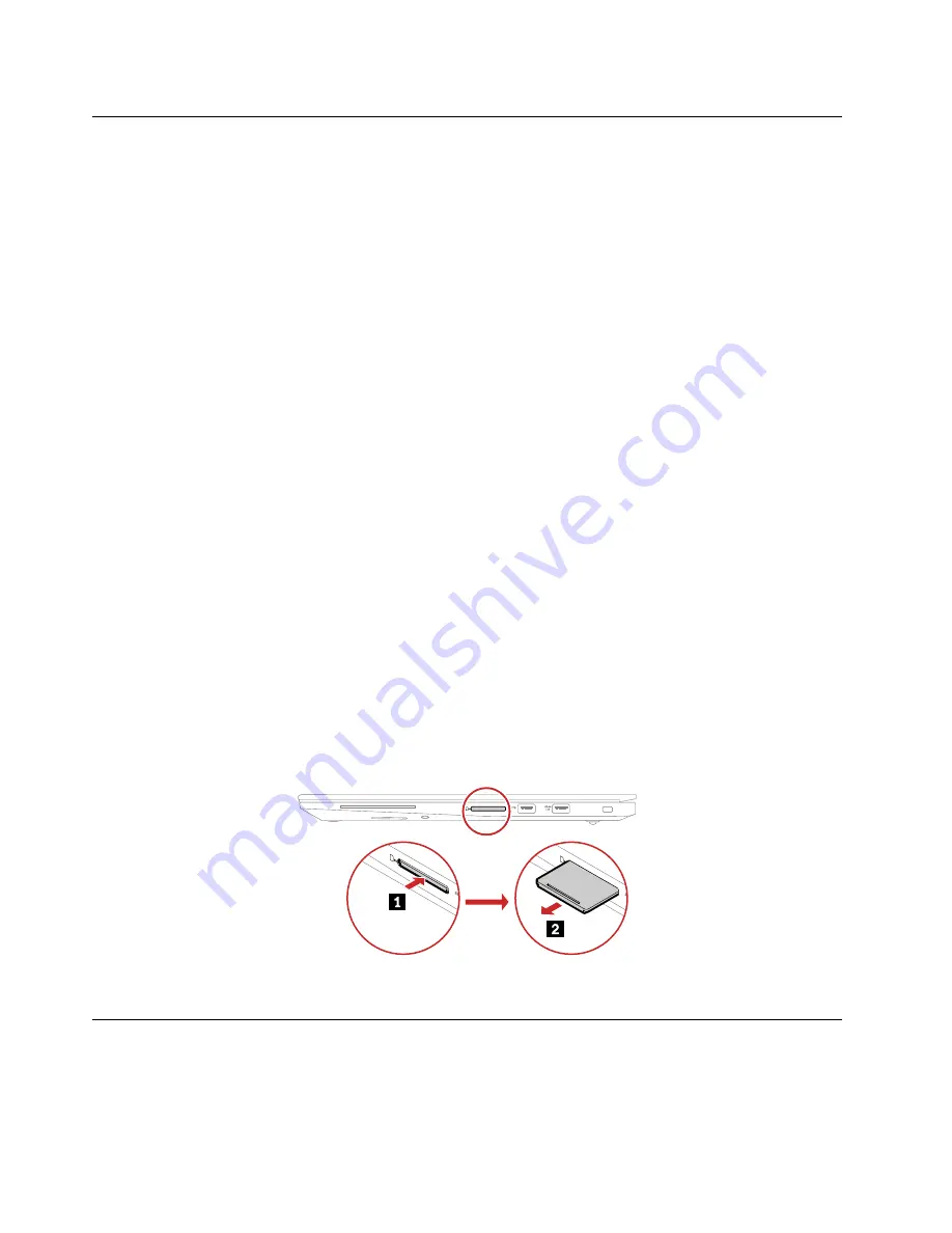
Removing the media card
If the computer has a media card installed, remove the media card before you start the servicing.
After you finish the servicing, ensure that you install the media card (if available) back into the computer.
Removing a major FRU
This section provides instructions on how to remove a major FRU.
62
P1 Gen 2, X1 Extreme and X1 Extreme 2nd Hardware Maintenance Manual
Summary of Contents for 20QT
Page 1: ...P1 Gen 2 X1 Extreme and X1 Extreme 2nd Hardware Maintenance Manual ...
Page 6: ...iv P1 Gen 2 X1 Extreme and X1 Extreme 2nd Hardware Maintenance Manual ...
Page 11: ...DANGER DANGER DANGER DANGER DANGER Chapter 1 Safety information 5 ...
Page 12: ...6 P1 Gen 2 X1 Extreme and X1 Extreme 2nd Hardware Maintenance Manual ...
Page 13: ...PERIGO PERIGO Chapter 1 Safety information 7 ...
Page 15: ...PERIGO DANGER DANGER DANGER DANGER Chapter 1 Safety information 9 ...
Page 17: ...VORSICHT VORSICHT VORSICHT VORSICHT Chapter 1 Safety information 11 ...
Page 19: ...Chapter 1 Safety information 13 ...
Page 20: ...14 P1 Gen 2 X1 Extreme and X1 Extreme 2nd Hardware Maintenance Manual ...
Page 21: ...Chapter 1 Safety information 15 ...
Page 22: ...16 P1 Gen 2 X1 Extreme and X1 Extreme 2nd Hardware Maintenance Manual ...
Page 23: ...Chapter 1 Safety information 17 ...
Page 24: ...18 P1 Gen 2 X1 Extreme and X1 Extreme 2nd Hardware Maintenance Manual ...
Page 25: ...Chapter 1 Safety information 19 ...
Page 26: ...20 P1 Gen 2 X1 Extreme and X1 Extreme 2nd Hardware Maintenance Manual ...
Page 30: ...24 P1 Gen 2 X1 Extreme and X1 Extreme 2nd Hardware Maintenance Manual ...
Page 36: ...30 P1 Gen 2 X1 Extreme and X1 Extreme 2nd Hardware Maintenance Manual ...
Page 55: ...Major FRUs Chapter 6 Locations 49 ...
Page 103: ...Installation steps of the LCD cable Chapter 8 Removing or replacing a FRU 97 ...
Page 113: ......
Page 114: ...Part Number SP40G76835 Printed in 1P P N SP40G76835 ...
Page 115: ... 1PSPXXXXXXXX ...