


PaveSmart 3D UM
28
Getting Started
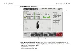
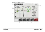
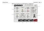
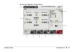
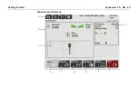
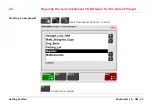
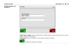
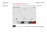
The Work dialog screen shows all the information needed while the machine is in
operation.
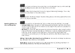
a)
Dashboard/Error messages
: the specific icon flashes yellow if a warning is detected or
flashes red if an error occurs. By pressing on the specific button additional information and
troubleshooting tips will be displayed.
1.) MPC1310 messages
2.) Communication messages
3.) Sensor messages
4.) Machine messages
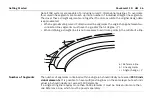
b)
Corrections
: indicates the required corrections for the four elevation cylinders of the mold
(left/right and front/rear) and the position of the mold (steer front/rear) relative to the
selected Reference Line, Slope Line and Working Offsets. For example, if the Left Front height
correction shows -0.013 (in m or ft), the machine has to raise the left front of the mold by
0.013 (in m or ft).
c)
Information
: provides information about the work progress like Stationing/Chainage, Speed,
Design Slope, Next Action and Sensor Information.
d)
Design Display
: shows the whole project and the current machine position. Click on the map
to select the desired Reference Line and Slope Line.
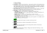
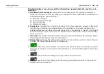
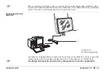
e)
Press and hold for at least 1 second to start Active Control. Control will only start if
all required sensors are connected, machine dimensions and Primary/Secondary control points
defined.
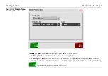
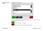
f)
opens the Sensor dialog to manage Robot and GPS sensors.
g)
opens the Offset dialog to set the working mold offsets relative to the selected
ReferenceLine and SlopeLine.
Summary of Contents for MCR-900
Page 1: ...Leica PaveSmart 3D User Manual Version 5 0 English ...
Page 11: ...How to use this Manual PaveSmart 3D UM 11 ...
Page 21: ...Getting Started PaveSmart 3D UM 21 Work Screen for Milling Machines a b d c e f g h i ...
Page 27: ...Getting Started PaveSmart 3D UM 27 Work Screen Mainline Concrete Paver a b c d f g h i j e ...
Page 30: ...PaveSmart 3D UM 30 Getting Started Work Screen Trimmer a b d c e f g h i j ...
Page 99: ...System Components Diagrams Software Description PaveSmart 3D UM 99 ...
Page 107: ...Troubleshooting PaveSmart 3D UM 107 ...
Page 136: ...PaveSmart 3D UM 136 Technical Data Mounting RAM mounting Parameter Data ...