background image

13

Leica CV5030 - Robotic Coverslipper

4.1

Location requirements

The  equipment  location  must  meet  the  following  requirements:

Stable,  plane,  vibration-free  lab  table.

Largely  vibration-free  floor.

Space  of  approx.  25  cm  on  the  left  side  of  the  unit  (to  open  the  side
door).

Space  behind  the  unit  for  connecting  the  fume  tubing.

Room  temperature  generally  between  +10   °C  and  +35  °C.

Relative  humidity  80%  maximum,  non-condensing.

The use of the unit in hazardous areas is not allowed.

4.2

Setup and initial operation

4.

Initial setup

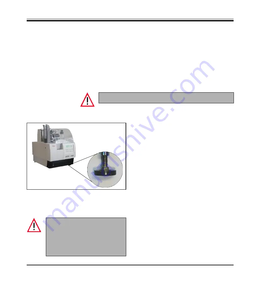
Fig. 3

Perform  the  repacking  of  the  unit  in  reverse
order  to  the  unpacking  instructions.  The  pack-
ing  material  should,  therefore,  always  be  kept
(unpacking  instructions  on  the  outside  of  the
transport  packaging).

Mountant  bottle  must  be  taken  from  the  unit.
Remove  all  residues  from  the  system  using  a
suitable  solvent.

The  unit  must  be  transported  in  upright  posi-
tion  only  as  indicated  by  labels  on  the  outside
of  the  transport  box.

To lift the unit, pick it up by reaching under the
sides  (at  least  2  persons  are  required—the
device  weighs  approx.  57  kg)  and  lift  it  onto  a
solid  laboratory  table.

Pull the protective plastic cover upwards to
remove  it.

Ensure  that  the  delivered  accessories  are
complete  in  accordance  with  the  order.

The  chemicals  used  in  the  Leica
CV5030  are  easily  inflammable  and
hazardous  to  health.  The  installation
location  of  the  CV5030  must  be  well-
ventilated;  there  should  be  no  igni-
tion sources there of any kind.

Adjust  the  height  of  the  threaded  feet  (Fig.  3)  to
ensure  that  the  unit  is  level  in  all  directions.

Summary of Contents for CV5030

Page 1: ...nstruction Manual Leica CV5030 Robotic Coverslipper V1 1 English 11 2002 Always keep the manual near the instrument Read it carefully prior to operating the instrument Leica CV5030 Robotic Coverslippe...

Page 2: ......

Page 3: ...are not to be considered as warranted characteristics of our products These are determined only by the contract provisions agreed between ourselves and our customers Leica reserves the right to chang...

Page 4: ...CV5030 17 5 1 Electrical connection 17 5 2 Key designations and their functions 17 5 3 Program flow 19 5 4 User MENU 21 5 5 Priming 24 5 6 Coverslipping 24 5 7 Interrupting the coverslipping process...

Page 5: ...n in parentheses refer to positions in illustrations Function keys to be pressed on the control panel are printed in boldface and with capital letters 1 Important information 1 2 Designated use The Le...

Page 6: ...to existing national regulations on accident prevention and environmen tal protection in the country where the unit is operated Device type All information contained in this instruction manual applies...

Page 7: ...d Transport and installation The unit must be transported in upright position only The unit must be connected only with the supplied power cable and only to a grounded power receptacle The protective...

Page 8: ...h broken glass Unit must be operated with vent or fume tubing and activated carbon filter must be as sembled and connected properly Warning against hazardous fire and poison through sol vent vapors Cl...

Page 9: ...erview Components functions 3 Unit components and specifications Fig 1 Unit cover On Off switch Control panel display Output rack guide Bottle with mountant Input door Leveling feet Maintenance door C...

Page 10: ...3 2 Functions of the control panel LED READY LEDBUSY LED PAUSE LED ERROR RELEASE COVERSLIP STANDBY RESPOND Acknowl edging an audible alarm RELEASE SLIDE PRIME Open dispens ing valve VENT MOUNTANT Bot...

Page 11: ...BU F 5A 1 mains cable D 1 mains cable USA C J 1 single open end wrench 13 1 activated carbon filter xylene 1 CV5030 instructions for repacking 1 Leica CV5030 instruction manual E F G S 2 nozzles 1x la...

Page 12: ...hput 1 slide in approx 9 s Slides catered for high quality slides with ground edges Coverslip magazine capacity depending on coverslip size 120 pcs 22 24mm x 60mm 160 pcs 22 24mm x 40mm Coverslips cat...

Page 13: ...ructions on the outside of the transport packaging Mountant bottle must be taken from the unit Remove all residues from the system using a suitable solvent The unit must be transported in upright posi...

Page 14: ...he sleeve of the cover plate behind the operating plate Connect the tubing from the lid of the mountant bottle with the pressure output in the cover plate behind the operating plate Place the insert a...

Page 15: ...side of the unit 2 Now release the Allen screw 2 and push the cover up 3 Insert the filter and tighten the screws in the reverse order Use the supplied tools for assembly 1 2 4 2 2 Coverslip collectio...

Page 16: ...ral hours overnight in the vent Screw the lid of the mountant bottle firmly onto the bottle Select the coverslip magazine 2 for the de sired coverslip type 22mm or 24mm wide Fill the coverslip magazin...

Page 17: ...tput maga zine PAUSE LED lights up Press START to continue Device parameters can be changed STOP interrupts the unit operation immediately ERROR LED lights up in red Use START to reinitialize the unit...

Page 18: ...take several seconds until the gripper opens The PRIME key opens the dispensing valve as long as the key is pressed blocked while the BUSY LED is lit The VENT MOUNTANT key vents the bottle with the mo...

Page 19: ...to accept a rack Dispenser located at P P i e not in the prime position after startup or when PRIME is pressed accompanied by characteristic audible signal Appears after pressing START if the dispense...

Page 20: ...accompanied by continuous audible signal 20s audible signal after completion of the process FINISHED remains on display until a key is pressed or the bath opened Bath not OK either no bath found vesse...

Page 21: ...he mountant volume is adjusted to suit the coverslip length START PAUSE switches to higher lower values RESPOND MENU A main screen STANDBY quits MENUs Setting of the mountant volume for the parameter...

Page 22: ...T PAUSE changes parameter set RESPOND Menu A STANDBY quits MENUs Coverslip position for parameter set n in this example 1 the value is relative NNN from 30 to 30 3 mm to 3 mm in individual steps 0 cor...

Page 23: ...MENUs Sets the limit value for the CS LOW display universal parameter ap plies to all parameter sets Procedure place coverslip stack with desired height in coverslip magazine Press START P P now moves...

Page 24: ...mountant bottle and dispensing valve by means of priming PRIME disappears from the display after initial pressing of the key at this time the coverslipping process can be started Place the slides in t...

Page 25: ...ty slot The display is erased after a few seconds READY mode Place the dispensing valve in the pause position prime container to prevent the nozzle from drying up It does not have to be performed afte...

Page 26: ...to the extraction position and can be re placed with empty racks If the output racks are raised to the extraction position all slides must be removed from them The RESPOND 2s key is used to modify th...

Page 27: ...zed Same state as that following the activation of the unit Interruption by pulling out the bath guide The unit finishes the coverslipping process of the current slide and pushes it into the output ra...

Page 28: ...a nism After receiving a new coverslip the process is automatically contin ued Output rack full The unit automatically switches to PAUSE mode after filling the last slot An audible alarm indicates tha...

Page 29: ...ntant volume and pressure 1 Histology Mountant Mountant Nozzle Coverslip size medium Stroke Volume Type Permount DPX Pertex CV Mount CV Ultra 2 Cytology Mountant Mountant Nozzle Coverslip size medium...

Page 30: ...of additional racks 6 2 Requests by the robotic color multistainer ST5020 Requests are permitted if the CV5030 is in READY mode or a rack is being processed and no interaction is required of the user...

Page 31: ...SE has the same function as described in section 5 3 as long as the bath guide is not pulled out the slide rack is removed by the TS5025 if the coverslipping process is continued or concluded The STOP...

Page 32: ...ns Empty coverslip magazine coverslip break and full output rack are handled as described in section 5 4 Following the processing the empty input rack is placed on the ramp of the TS5025 Error in the...

Page 33: ...the mountant from the mountant bottle Clean the bottle dispensing valve and nozzle by rinsing with a suitable solu tion Empty the bath into a tight sealing container and discard according to existing...

Page 34: ...f the feeder mechanism and the face of the capacitive sensor between the suction devices must also be checked for con tamination during the suction check and cleaned if necessary Mountant buildup must...

Page 35: ...y Clean nozzle x Clean walking beam x Remove mountant residues from output rack x Check prime container empty or fill if necessary x Replace activated carbon filter x x Check suction cups clean or rep...

Page 36: ...it stops at that point all unit func tions are available again BATH NOT PRESENT It appears if the bath which is the first to be moved completely to the rear is not recognized after pressing START In...

Page 37: ...cause of the prevention This prevention must be removed for the transfer to be successful addi tional request through ST5020 after 60 s COVER SLIP BROKEN A coverslip at the coverslip transport arm is...

Page 38: ...ectronics ST5020 CONTROL Indicates that the most recently processed input rack was received by the ST5020 TS5025 WAITING An input rack was transferred from ST5020 to TS5025 but it could not be process...

Page 39: ...sport subgroup Error 2 53 Slider Please contact our technical service Slider output lift subgroup Error 2 54 Slider Please contact our technical service Transfer station Error 2 61 Transfer station Pl...

Page 40: ...nical service Slider Error 4 51 Sledge Reinitialize or contact our technical service Error 4 52 Sledge Reinitialize or contact our technical service Error message Area of problem Action From CPU versi...

Page 41: ...or 4 61 Transfer Reinitialize or contact our technical service Error 4 62 Rack Reinitialize or contact our technical service Error 4 63 Home position Reinitialize or contact our technical service Erro...

Page 42: ...coverslipping 4 bottles 250 ml ea in carton Leica ST Ultra mounting medium Leica ST Ultra was developed as a xylene replacement for histological specimen mounting paraffin removal as well as manual an...

Page 43: ...or 30 slides Leica CV5030 container for Leica slide racks for 20 slides Leica CV5030 container for Sakura slide racks for 20 slides Leica CV5030 container for Microm slide racks for 20 slides Leica CV...

Page 44: ...s of your Leica sales organization or the organization from which you have purchased the contractual product shall apply exclusively Service information If you are in need of technical customer servic...

Reviews: