background image

45

Leica CM3600 XP

Software

6

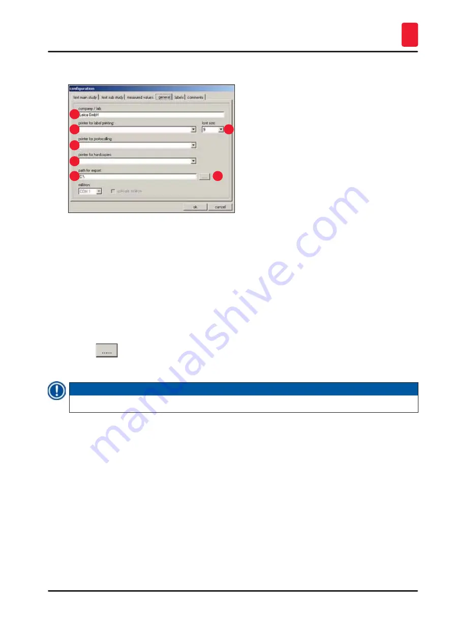
General tab 

(

 Fig. 35-

4

)

1

3

2

7

4

5
6

Fig. 38 


The 

General

 tab contains the following fields:

1

Company/lab

Enter the name of the company or the laboratory. This is displayed in 

the 

Status bar

 on the right side, see 

(

 p. 29 – 6.2 Description of the 

window elements)

.

2,4,5 Printer selection

Clicking on the respective line opens a drop-down menu. The printer 

selection takes place here, if one is present.

3

Font size

Here you can select the desired font size for the labels.

6

Path for export

Clicking the 

Export path

 icon opens the 

Path selection for data export


dialog box. A directory in which data (main studies and substudies, 

measured values, events and alarms) is to be stored can be selected here. 

The export file is stored as a text file.

7

Note 

If no printer can be selected, a printer has to be installed later on the present operating system.

Labels tab 

(

 Fig. 35-

5

)

You can enter the text for the labels in this tab, see 

(

 p. 60 – 6.15 Printing labels)

.

•  9 lines of 50 characters each can be entered. Lines where no characters have been entered are printed 

as empty lines.

• 

Clicking on the 

Bold

 checkbox in the corresponding line activates bold print.

•  Specific information can be entered during label printing for the output of predefined variables 

commencing with the special character "@".

Summary of Contents for CM3600 XP

Page 1: ...uctions for Use English Order No 14 0417 80101 Revision H Always keep this manual with the instrument Read carefully before working with the instrument Version 6 9 Revision H 11 2020 Leica CM3600 XP Cryostat ...

Page 2: ......

Page 3: ...llustrations and other information regarding the contents or technical details of the present Instructions for Use are not to be considered warranted characteristics of our products These are determined only by the contract provisions agreed between ourselves and our customers Leica reserves the right to change technical specifications as well as manufacturing processes without prior notice Only i...

Page 4: ... requirements 21 4 1 Site requirements at place of installation 21 4 2 Electrical connections 22 4 3 Other connections 22 5 Installation 23 5 1 Unpacking and installation 23 5 2 Standard delivery 23 5 3 Port and switch panel 24 5 3 1 Port and switch functions 25 5 3 2 Fuses 26 5 4 PC 27 6 Software 28 6 1 Start and log in procedure 28 6 2 Description of the window elements 29 6 3 Initialization 31 ...

Page 5: ... illumination 55 6 10 Section documentation 55 6 11 Photo mode 59 6 12 Screen printout 59 6 13 Help 59 6 14 Save 59 6 15 Printing labels 60 6 16 Foot switch 60 6 17 User log in log out 60 6 18 Quitting the application 60 7 Operating the Leica CM3600 XP 61 7 1 Check list 61 7 2 Switching the instrument on 61 7 3 Starting the software 61 7 4 Setting the chamber temperature 62 7 5 Specimen stages 62 ...

Page 6: ...n 6 9 Revision H Table of contents 8 Cleaning and Maintenance 76 8 1 Cleaning 76 8 1 1 Removing the microtome 76 10 Warranty and Service 82 11 Decommissioning and Disposal 83 12 Decontamination Confirmation 84 ...

Page 7: ...nput screen are displayed as bold gray text Symbol Title of the symbol Keys and switches on the instrument Start Description Keys and switches on the instrument that are supposed to be pressed by the user in various situations are displayed as bold gray and underlined text Symbol Title of the symbol Attention Description Indicates the need for the user to consult the Instructions for Use for impor...

Page 8: ...ufacturing date Description Indicates the date when the medical device was manufactured Symbol Title of the symbol Article number Description Indicates the manufacturer s catalog number so that the medical device can be identified Symbol Title of the symbol Serial number Description Indicates the manufacturer s serial number so that a specific medical device can be identified Symbol Title of the s...

Page 9: ...shipment is immediately detectable and can be proven definitively Note When delivering the instrument the recipient must check that the tilt indicator is intact The responsible Leica representative must be notified in the case that one or all indicators have been triggered 1 2 Instrument type All information provided in these Instructions for Use applies only to the instrument type indicated on th...

Page 10: ...s in these Instructions for Use Warning Any use of the instrument not described in these Instructions for Use is considered improper If you wish to use the instrument for special applications or modes of operation not listed in this manual it is absolutely necessary that you contact your local Leica representation prior to doing so Otherwise you will loose the Leica warranty on your instrument Onl...

Page 11: ...y stop switch to stop the microtome immediately 5 Window The window is heated and can be opened completely 6 Microtome in the cabinet The microtome is used to section the specimens 7 Chamber lid The chamber lid can be opened completely for maintenance and cleaning work on microtome and or cryochamber 8 Cabinet The cabinet contains the cryochamber which houses the microtome 9 Knee lever The knee le...

Page 12: ...arbide knife 160 mm Knife holder for disposable blade holder 160 mm Knife 160 mm with facet angle of 20 35 Control unit The Leica CM3600 XP is equipped with a commercially available computer with monitor keyboard and mouse For further information please refer to the manual of the PC Operating system Windows Software CM3600 XP version 3 2 2 Dimensions and weights Inner cryochamber L x H x W 1650 x ...

Page 13: ...ominal supply voltages 200 V AC Nominal frequency 50 Hz Line voltage tolerance 10 Power draw 2400 VA Automatic cutout 2 x 8 A 1 x 10 A Power safety switch UL listed Power plug CEE in accordance with IEC 60309 Mennekes ProTOP 148A fits to socket type 1632 200 V 60 Hz Nominal supply voltages 200 V AC Nominal frequency 60 Hz Line voltage tolerance 10 Power draw 2400 VA Automatic cutout 2 x 8 A 1 x 10...

Page 14: ...degree 2 Overvoltage category II Noise information A weighted noise level 78 5 dB A Distance between sound meter and instrument 1 meter Measuring uncertainty 1 5 dB A Instrument setting for measurement Normal instrument operation with extraction Warning The user must wear hearing protection when using the extraction 2 3 Instrument parts The Leica CM3600 XP consists of a sliding microtome in a larg...

Page 15: ...stroke of the specimen sledge the stepper motor automatically carries out a knife retraction movement programmable between 50 and 250 μm This protects both the knife blade and the specimen surface from being damaged Before starting the next sectioning stroke the motor lowers the knife towards the specimen surface by the selected sectioning feed plus the set value for knife retraction Trimming is p...

Page 16: ...equirements for electrical equipment for measurement control and laboratory use To maintain this condition and ensure safe operation the user must observe all notes and warnings contained in these Instructions for Use Note For current information about applicable standards please refer to the CE declaration for the instrument and to our Internet site http www LeicaBiosystems com Warning The protec...

Page 17: ...op switch see p 18 3 3 1 Emergency stop switch The chamber lid must be closed at all times when the instrument is operated as otherwise the emergency stop switch is not accessible The user must be able to reach the specimen easily while working on the microtome During all work wear close fitting clothing and use safety glasses Caution when using the foldaway extraction Before you manipulate the sp...

Page 18: ...or inside the cryochamber wear the safety gloves provided see p 23 5 2 Standard delivery Prior to any work involving the knife or the microtome or in the cryochamber swing the knee lever upwards see p 19 3 3 2 Knee lever 3 3 Safety features 3 3 1 Emergency stop switch The Leica CM3600 XP is equipped with an Emergency stop switch Fig 2 1 located on the cabinet to the left of the window To activate ...

Page 19: ...then has to be confirmed in the alarm list see p 52 6 8 Alarm list and p 53 6 8 1 Work space Afterwards the sectioning program has to be reselected see p 35 6 4 7 Section program 3 3 2 Knee lever 1 Fig 3 Never leave the Leica CM3600 XP unattended when the knee lever Fig 3 1 is folded out to prevent the microtome from being set in motion accidentally Warning Always swing the knee lever upwards befo...

Page 20: ...80 Warning You must make sure that the window has been locked before the chamber lid is opened 3 3 4 Cabinet 3 Fig 5 Before opening the chamber lid you must first close the window and lock it with the locking knob Fig 4 2 When opening the chamber lid make sure the lid retainer Fig 5 3 engages to prevent the chamber lid from falling Warning When opening the chamber lid the lid retainer must engage ...

Page 21: ...and extreme variations in temperature Installation elevation up to 2 000 m above sea level If possible at all the room should be air conditioned If ambient conditions are not maintained as specified instrument performance may be negatively affected lowest specified temperature may not be reached frost may accumulate All transport paths for the Leica CM3600 XP must be at least 1 50 m wide especiall...

Page 22: ... not be reached 4 2 Electrical connections Country Europe USA Japan Installation cord cross section 2 5 mm2 2 5 mm2 2 5 mm2 Fuse protection connection 16 A 380 V 25 A 208 V 25 A 200 V Power cable length is 3 m A second protective conductor terminal is located on the instrument Both terminals must be used There must not be any differences in potential between the two protective conductor terminals ...

Page 23: ...ouse network cable and dongle 14 0417 43799 1 Flat screen 14 0417 33846 1 Mouse pad 14 0417 29029 1 Disposable blade holder 157 AR 14 0417 26152 1 Dispenser with 10 disposable blades type H45 L 14 0216 26153 1 Sectioning tool 150 mm 14 0417 19039 1 Positioning tool for knife 14 0417 19141 1 Levelling device for specimen adjustment 14 0387 18191 1 Positioning tool for use with disposable blade hold...

Page 24: ... 40426 1 Bottle 500 ml Isoflex PDP 38 cooling oil for Leica CM3600 XP 14 0336 06101 1 Instructions for Use printed English with language CD 14 0417 80200 14 0417 80001 Note Check the delivery carefully against the packing list delivery note and your order Should there be any deviations please contact the Leica sales office handling your order or your Leica dealer 5 3 Port and switch panel 1 6 2 7 ...

Page 25: ...of section thickness documentation GLP Connection for compressed air Fig 7 3 Connection of compressed air hose to extraction unit GFCI switch Fig 7 4 Protects the entire instrument Main power switch Fig 7 5 Switch in the 0 position disconnects the instrument from the power supply Switch for local alarm signal Fig 7 6 To activate the local alarm function press the alarm signal switch The green LED ...

Page 26: ...tched is 250 V Because a compatible plug is provided with the instrument the user must make a corresponding connection onsite Warning Important The connection of an alarm to the plug provided must be carried out by trained personnel if the voltages are greater than 33 V AC or 70 V DC Wiring the connection for external alarm in the instrument CA 6 21 24 22 Rel g1 1 5 3 Fig 8 The wiring diagram show...

Page 27: ...tout Fig 10 9 is triggered the switch will be in the lower position Flip it upwards to switch it back on Fuse protecting the main power switch Fig 11 10 10 Fig 11 After the automatic cutout has been activated it will be in the lower position Flip it upwards to switch it back on 5 4 PC The Leica CM3600 XP is equipped with a commercially available computer with monitor keyboard and mouse For further...

Page 28: ...in screen 1 2 3 Fig 12 Type the user name Fig 12 1 in the identification field Type the correct password Fig 12 2 in the password field Click the Ok button Fig 12 3 to complete the login After successfully logging in the Main window will open for additional information refer to Chapter p 32 6 4 Main window Note After 5 failed registration attempts access to the unit will be locked Only an administ...

Page 29: ...idual software functions at the click of a mouse by clicking on an icon When clicking on an icon the corresponding window will open up The selected icon lights up green while active Toolbar icons Clicking on the icon opens the Main window which also opens up the start window after completion of the start and log in procedure Clicking on the icon opens the Parameter setting window Clicking on the i...

Page 30: ...oot switch When activated the icon will light up in green and the current sectioning data will be saved The Stop icon appears as soon as the Emergency stop switch has been pressed The icon flashes red The instrument will be not be operational until the operator has acknowledged the corresponding error message in the Alarm list window see p 52 6 8 Alarm list Clicking on the Log off icon logs off th...

Page 31: ...de The Safety check initialisation window will open If you can answer Yes to a confirmation prompt Fig 15 2 and have carried out the required actions check the checkbox next to it After successfully answering all queries click the Ok button Fig 15 3 1 Fig 14 2 3 Fig 15 The microtome will then be initialized The knife holder moves to the uppermost position The microtome sledge moves to the end posi...

Page 32: ...up automatically after completing the start and log in procedure or by clicking on the Main window icon 1 6 2 7 3 8 4 5 10 Fig 16 1 Chamber temperature 6 Extraction 2 Time 7 Section program 3 Automatic defrost 8 Sledge speed 4 Automatic dehydration 9 Mode 5 Knife movement 10 Cutting window 6 4 1 Chamber temperature Fig 17 Displays actual or set chamber temperature See p 38 6 5 1 Parameter settings...

Page 33: ...on process Clicking on this button once more stops dehydration When activated the button blinks yellow If a reduction in temperature is to be carried out during automatic dehydration the required settings have to be made in the Parameter setting window see p 38 6 5 1 Parameter settings 6 4 5 Knife movement Displays section and retraction thickness The Actual position Fig 21 13 displays the current...

Page 34: ...upwards until reaching the upper limit position To stop the knife movement click on the button once more When activated the button will light up in green 19 Knife down Clicking on this button moves the knife holder fast downwards for a short while If you click on and hold this button the knife holder will continue to move downward until the left mouse button is released While active the button lig...

Page 35: ...vates or deactivates intermittent extraction When activated the button will light up in green Note The extraction function can only be activated if an extraction unit is connected to the instrument 6 4 7 Section program Displays set or actual number of sections To modify any of the settings mouse click on the corresponding button Entries are completed by pressing the Enter button 24 25 Fig 23 Prog...

Page 36: ...carried out after startup to be able to work with the instrument after it is switched on see p 31 6 3 Initialization Displays current sectioning or return stroke speed in mm s millimeters per second To modify any of the settings click on the corresponding value Buttons prior to initialization Buttons after initialization 1 2 4 3 Fig 25 1 Init Clicking on this button opens the Safety check initiali...

Page 37: ... sledge position is graphically displayed by the green line Clicking on the Actual position display changes the setting The icons on the left and right side of the scale Fig 26 4 and Fig 26 5 are used for adjusting the left and or right block half to the value of the current microtome sledge position according to the display Left block edge button Fig 26 4 Clicking here opens up an entry window Th...

Page 38: ...gs window is divided as follows 1 Parameter settings 4 Initialization 2 Password list 5 Language selection 3 Configuration 6 Reference voltages 6 5 1 Parameter settings Different settings can be selected using the Parameter setting menu 1 6 12 2 8 13 3 9 4 10 5 11 18 14 19 15 16 20 17 21 7 Fig 28 ...

Page 39: ... this display opens the System time dialog box Fig 29 Clicking on a subarea of the display day month year hour or minutes lets you change the setting The entry must be confirmed by pressing the Ok button Start time 1 of the defrost Fig 28 5 Fig 30 Displays start time of the 1st automatic defrost cycle Clicking on this display opens the Defrost time 1 dialog box Fig 30 Click on individual parameter...

Page 40: ...o use this function efficiently it is advisable to remove the section waste from the cryochamber before the start of the dehydration Dehydration T reduction Fig 28 11 Displays temperature reduction for dehydration Click on this display to change the currently selected value Values from 0 20 K can be selected Section thickness Fig 28 12 Displays section thickness Click on this display to change the...

Page 41: ...see p 43 6 5 3 Configuration 6 5 2 Password management Note To access the User configuration the registered user must be an administrator 1 6 2 3 4 5 Fig 33 The User configuration display is divided into the following columns 1 No Displays the program controlled running number 2 Active Displays status of the user selected Active users are displayed with an X 3 User name Displays the user name whic...

Page 42: ...step can a user successfully register via the start and log in procedure 3 User name Enter the desired user name A maximum of 10 characters numerical or alphanumerical can be entered 4 Full name Enter full first and last name of user 5 User rights Click on the User rights line to open a drop down menu The user property Administrator or User can be selected 6 7 Password and Confirm password Enter t...

Page 43: ... saves the entries and closes the Configuration window 8 Cancel Clicking on this button closes the Configuration window without saving any of the changes made Text main study Fig 35 1 and Text substudy Fig 35 2 tabs The structure of the two tabs is identical A header and 7 freely selectable comments for each main study or substudy can be defined The text entered into the 8 input fields is copied i...

Page 44: ...lecting a main study or substudy The configuration of a main study or substudy is covered in Chapter p 55 6 10 Section documentation Fig 37 The following measured values can be selected Set chamber temperature target value Chamber temperature actual value Alarm temperature Section thickness set value Section thickness actual value Knife holder position Dehydration Comment ...

Page 45: ...he Path selection for data export dialog box A directory in which data main studies and substudies measured values events and alarms is to be stored can be selected here The export file is stored as a text file 7 Note If no printer can be selected a printer has to be installed later on the present operating system Labels tab Fig 35 5 You can enter the text for the labels in this tab see p 60 6 15 ...

Page 46: ... line 2 q Substudy comment line 7 d Current date t Current time e Main study comment line 3 0 Measured value no of section f Main study comment line 4 1 Measured value date of section g Main study comment line 5 2 Measured value time of section h Main study comment line 6 3 Measured value target cryochamber temperature i Main study comment line 7 4 Measured value actual cryochamber temperature j S...

Page 47: ...ialog box Any entry made is not saved 2 Change Clicking on this button opens the Comment on section dialog box The existing entry can be changed 3 Delete Clicking on this indication opens a safety query dialog If the safety query is confirmed by clicking on Ok the comment will be permanently deleted 6 5 4 Reference voltages Fig 42 Displays the current reference voltage in volts is inactive Buttons...

Page 48: ...ears in the Mode field Clicking the Init button opens the Safety check initialisation dialog box see p 31 6 3 Initialization 6 6 Temperature curves Clicking the Temperature curves icon opens the window 1 2 Fig 45 The window contains the following areas 1 Work space 2 Diagram Note The Temperature curves display is only for failure analysis by Leica service technicians ...

Page 49: ...k to the original position 5 6 Start and Stop Clicking on one of these buttons starts or stops the recording of measured values in the diagram 7 8 and Clicking on one of these buttons starts a forward or backward scroll in the diagram Clicking on one of the check boxes in the work space the 8 temperature sensors of the instrument can be displayed individually in the diagram The font color of the c...

Page 50: ...se create a zoom box on the area to be enlarged by dragging the mouse cursor to the right and downwards at the same time Release the left mouse button The selected diagram zoom box is enlarged All measured values activated via the check boxes in the work space are displayed 6 7 Chronological event list Click on Event list icon to open the corresponding window 1 2 Fig 48 The working area is divided...

Page 51: ...he Month header In the Time filter field you can now see the start time left and end time right of the selected time interval You can set an additional filter in the Text filter field Click on Ok to close the dialog box and display the desired alarm messages in the events list Click on Cancel to close the window without saving any of the changes made 2 Comment Clicking on an event in the event tab...

Page 52: ...ame of the user who was logged in when the event occurred 3 Message Event messages short description of event 4 Comment Display of comments related to the events see p 51 6 7 1 Work space Note Individual events messages will be displayed in the events list for a maximum of 90 days from the date when the event occurred After that the data will be saved into a text file see Fig 38 6 and Fig 38 7 6 8...

Page 53: ...vents concerning the program are saved If the Emergency stop switch has been activated the reset must be acknowledged in the alarm list Fig 53 3 Afterwards the section program has to be reselected see p 35 6 4 7 Section program 6 8 1 Work space 1 3 5 6 2 4 Fig 53 In the work space the following parameters can be selected 1 Filter Clicking this button opens the Filter dialog box see p 51 6 7 1 Work...

Page 54: ... 5 Print Clicking on this button creates a screen printout of the current display 6 Export file Clicking this button exports the alarm list to a text file see Fig 38 6 and Fig 38 7 6 8 2 Alarm list 1 2 4 6 3 5 Fig 54 The table is divided into the following columns 1 Occurred Displays date and time when the alarm started 2 Cleared Displays date and time when the alarm stopped 3 Confirmed Displays d...

Page 55: ...d control unit If the problem recurs call Service Technician Error 06 Not defined Error 07 Emergency stop activated Deactivate the emergency stop Error 08 Stepper motor step error Inform Service Technician Error 09 Refrigerating system pressure exceeded Check the air circulation between the condenser and the control unit Check the distance of the instrument to the wall at least 50 cm If the proble...

Page 56: ...or substudies in a tree diagram For navigation purposes click on the preceding plus or minus sign 1 2 3 4 Fig 56 The different study types are identified by the preceding colored folder symbols 1 Yellow folder icon Collective folder for main studies 2 Green folder icon Main studies 3 Blue folder icon Substudy 4 Saved yellow folder icon Collective folder for saved main studies ...

Page 57: ... divided into the following columns 1 No Running number automatically allocated by the application 2 Date Date when the main study was created 3 Main study name Name of main study To create a new main study or substudy proceed as follows Right click on a spot anywhere in the upper table with the mouse A context menu will open up Select the New menu item A dialog box for a new main study or substud...

Page 58: ...erature at the time the section was made 5 T error Alarm temperature at the time the section was made 6 Set section thickness Set section thickness at the time the section was made 7 Actual section thickness Actual section thickness at the time the section was made 8 Knife holder position Knife holder position at the time the section was made 9 Dehydration Time when dehydration started finished 10...

Page 59: ... microtome sledge exactly for one or more photos to be taken after each section The settings for the Photo position dwelling time and the Photo position triggering time are configured under the Parameter setting Photo position dwelling time To define how long the microtome sledge will remain stopped in the camera position Photo position triggering time Time until the camera actually takes a photo ...

Page 60: ...he optional foot switch connected to the instrument i e documentation of the last section carried out will be saved when the foot switch is pressed Note The foot switch cannot be used without first activating the Save icon 6 17 User log in log out Clicking on the symbol logs off the user currently logged in Clicking again causes the start and login window to appear see p 29 6 2 Description of the ...

Page 61: ... 3 Adjust the cryochamber temperature and the sectioning temperature p 62 7 4 Setting the chamber temperature 4 Insert the specimen stage p 62 7 5 Specimen stages 5 Insert the knife p 65 7 6 Knife 6 Set the trimming value p 70 7 7 Setting the trimming parameters 7 Change the knife p 65 7 6 Knife 8 Set the sectioning parameters p 70 7 8 Setting the sectioning parameters 9 Dehydrate the specimen p 7...

Page 62: ... with separate ball and socket joint Fig 61 Specimen stage orientable with integrated ball and socket joint Fig 62 Specimen stage non orientable Fig 63 When inserting the specimen stages bear in mind the following Prior to sectioning it is important to ensure that the specimen temperature has adjusted to the set sectioning temperature approx 20 C To place the frozen specimen including the specimen...

Page 63: ...all joint To insert the specimen stage orientable with ball and socket joint proceed as described below The specimen holder orientable with ball joint is inserted the same way Required tools Open end wrench size 17 Proceed as follows Use the knee lever to move the sledge to the right side reversal position see p 36 6 4 9 Operation mode and p 19 3 3 2 Knee lever Observe the safety notes in Chapter ...

Page 64: ...e the sledge to the right side reversal position see p 36 6 4 9 Operation mode and p 19 3 3 2 Knee lever Observe the safety notes in Chapter p 62 7 5 Specimen stages Open the window see p 20 3 3 3 Window Remove the screw Fig 68 1 Lift off the T piece Fig 68 2 and support ring Fig 68 3 Remove the screws Fig 69 4 and bases Fig 69 5 located on the right and left side of the sledge 1 2 3 Fig 68 4 5 Fi...

Page 65: ... position which is most appropriate for your purpose and that ensures the best safety Prior to any work involving the knife or the microtome or inside the cryochamber activate the Emergency stop switch see p 18 3 3 1 Emergency stop switch For any work involving the knife or the microtome or inside the cryochamber wear the safety gloves provided see p 23 5 2 Standard delivery Prior to any work invo...

Page 66: ...dard knives To insert a standard knife proceed as follows Required tools Allen key size 4 Proceed as follows Use the knee lever to move the sledge to the right side reversal position see p 36 6 4 9 Operation mode and p 19 3 3 2 Knee lever Observe the safety notes in Chapter p 65 7 6 Knife Open the window see p 20 3 3 3 Window 1 2 3 4 Fig 74 ...

Page 67: ...lastic pegs Fig 75 7 press the knife Fig 75 3 into the correct position Tighten the screws Fig 74 1 Adjust the knife angle see p 69 7 6 3 Adjusting the knife angle 7 6 2 Inserting the disposable blade holder with disposable blade To insert the disposable blade holder with disposable blade proceed as described below Required tools Allen key size 4 Allen key size 2 5 Proceed as follows Use the knee ...

Page 68: ... 3 onto the base Fig 76 4 Attach the pressure plate Fig 76 2 to the disposable blade holder Fig 76 3 Insert and tighten the screws Fig 76 1 Loosen the screws Fig 77 9 of the disposable blade holder Fig 76 3 Insert the disposable blade Fig 76 5 The disposable blade is in the correct position when the disposable blade fits close to the limit stop of the disposable blade holder Fig 76 3 ...

Page 69: ...7 The two plastic pegs Fig 77 8 press the disposable blade holder Fig 76 3 into the correct position Tighten the screws Fig 76 1 Adjust the Knife angle see p 69 7 6 3 Adjusting the knife angle 7 6 3 Adjusting the knife angle Required tools Allen key size 5 Proceed as follows Observe the safety notes in Chapter p 65 7 6 Knife Loosen the screws Fig 78 1 Rotate the knife holder Fig 79 2 and set the d...

Page 70: ...Setting the sectioning parameters Proceed as follows Open the Main window in the software and then set the Manual operating mode Afterwards adjust the section thickness and the sectioning window see p 32 6 4 Main window 7 8 1 Sectioning the specimen For the sectioning procedure you need brush pressure plate and special section collecting tape and depending on the application a dehydration frame No...

Page 71: ...w fix the tape in place with a cooled brush paper towel or cotton wadding Never touch the specimen block face with your hands Hold the left end of the tape in your left hand Drive the microtome gently until some of the embedding medium is apparent on the left edge of the tape Use the pressure plate to aid in pressing the tape onto the block surface To do this press the pressure plate firmly on the...

Page 72: ... field of the main window To activate the button the knife holder is first to be brought to the highest position 100 000 200 000 μm using the user interface Fig 80 2 The knife holder must then be manually shifted into the desired position see p 74 7 10 3 Knife holder height adjustment and p 75 7 10 5 Sectioning thick blocks The 200 button works as a switch Clicking one time button is illuminated i...

Page 73: ...roove match the upper edge of the knife holder see Fig 83 Warning Under no circumstances can the knife holder be set to a lower position as this can cause serious damage to the instrument Fig 82 6 7 7 Four knurled screws Fig 82 6 and four clamping levers Fig 82 7 on the front hold the knife holder in its position and enable a fast height changeover 100 mm to 200 mm on the columns The temperature s...

Page 74: ...83 2 in the support columns in the 100 mm position or all the way at the top for the 200 mm position see Fig 85 Then re tighten the 4 clamping levers Fig 82 7 and the four knurled screws Fig 82 6 7 10 4 Uninstalling the knife holder Warning Before the knife holder can be uninstalled the temperature sensor Fig 84 4 has to be disconnected 4 5 Fig 84 To loosen the temperature sensor swing the locking...

Page 75: ...ld see p 36 6 4 9 Operation mode Carry out the sectioning of the product as described in Chapter p 70 7 8 1 Sectioning the specimen Once the measuring position reaches 100 000 μm interrupt sectioning recording for deactivating the Save menu item see Fig 86 under Extras in the study and the switch over the knife holder This requires putting the support columns back into the highest position Fig 85 ...

Page 76: ...crotome use commercial alcoholic disinfectants or alcohol The outer surfaces of the cryochamber and the control unit can be cleaned with mild household cleaners 8 1 1 Removing the microtome Note Normally it is not necessary to extract the microtome from the cryochamber However if you wish to lift the microtome out of the cabinet i e for thorough cleaning it is strongly recommended to use an overhe...

Page 77: ... that the spacer rings Fig 87 3 between the bracket Fig 87 4 and the microtome Fig 87 5 do not get lost Fold down the belt covers Fig 87 6 Disconnect the connections Fig 87 7 on the left side of the cabinet not on the microtome Fasten cables or straps that have a sufficient carrying capacity to the carrying handles Fig 87 8 Carefully lift the microtome Fig 87 5 out of the cabinet using the crane I...

Page 78: ... level Unscrew both covers Fig 88 1 The oil level must always be above the small capillary tubes Fig 88 2 Filling up the oil reservoirs Unscrew both covers Fig 88 1 and refill the PDP 38 low temperature oil order number see p 80 9 1 Ordering information Then screw both covers Fig 88 1 back on 3 3 Fig 89 Oiling the sledge guides The sledge guide Fig 89 3 is to be oiled with PDP 38 low temperature o...

Page 79: ...ed by the user The start time is freely selectable see p 38 6 5 1 Parameter settings Automatic defrost II If the Automatic defrost cycle I is not sufficient high humidity high ambient temperature defrost cycle II is to be activated in addition see p 38 6 5 1 Parameter settings Manual defrost This defrost cycle can be activated manually and starts immediately see p 33 6 4 3 Automatic defrost ...

Page 80: ...frame 120 x 200 mm 14 0022 50125 Embedding frame 120 x 250 mm 14 0417 19632 Embedding frame 150 x 450 mm 14 0022 50127 Disposable blade system for large surface cryosections Leica disposable blade holder 157 AR for disposable blades type H 45 L 14 0417 26152 1 dispenser with 10 H 45 L disposable blades with special coating 45 157 mm length cannot be used with other blade holders or instruments 14 ...

Page 81: ...ica CM3600 XP 14 0022 50192 Dehydration accessories Dehydration frames plastic for Leica CM3600 XP 14 0417 32995 Frame holder for 4 dehydration frames for Leica CM3600 XP 14 0417 32996 Other accessories Section waste tray 14 0417 32980 Tray 14 0417 32993 Height adjustment frame 100 mm assembly 14 0417 33970 Service agreements Maintenance contract Leica CM3600 XP 14 0417 32590 Application training ...

Page 82: ...y terms of your Leica sales organization or the organization from which you have purchased the contractual product shall apply exclusively Service information If you are in need of technical customer support or spare parts please contact your Leica representative or the Leica dealer where you purchased the instrument Please provide the following information Model name and serial number of the inst...

Page 83: ... using biohazardous specimens Thorough disinfecting is required before re commissioning or disposal e g multiple cleaning steps disinfection or sterilization Dispose of the instrument in compliance with the applicable laboratory specifications Contact your Leica representative for more information Instrument components such as the computer monitor etc that are labeled with the crossed out dust bin...

Page 84: ...he product menu This template must be used to enter all required data If a product is returned a copy of the completed and signed decontamination certificate must either be enclosed or handed over to a service technician The user shall be responsible for products that are returned without a completed decontamination certificate or with a missing decontamination certificate Return shipments that ar...

Page 85: ......

Page 86: ...w LeicaBiosystems com Version 6 9 Revision H 11 2020 Leica Biosystems Nussloch GmbH Heidelberger Strasse 17 19 69226 Nussloch Germany Tel 49 0 6224 143 0 Fax 49 0 6224 143 268 Web www LeicaBiosystems com ...

Reviews: