Group 5
Transport/Start up
Page 59
JET3 Series
Release 2.02
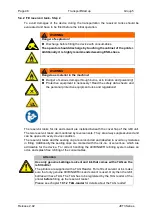
5.5.5 Interface X3 - Digital outputs
8 outputs which can be freely selected are available for special functions. The outputs 1-
3 are predefined as a standard and should be not changed.
Output 1 = Print stop error
Output 3 = Ready to print
Output 2 = Refill warning
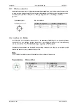
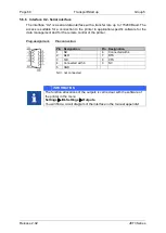
Plug assignment:
Pin connection:
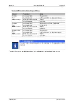
Specifications Output 1-8:
Parameter
Value
Driver type
24V high side driver
ON = +24V
OFF = high resistance
Output current
max. 700mA/output
max. 700 mA totally
(1)
Max. switching frequency
2 kHz
(2)
Max. delay time
100µs
Turn on resistance
max. 0,28 Ohm
Features
Short-circuit-proof
Overcurrent- and excess temperature
–
proof
INFORMATION
The function allocations of the outputs is carried out with the software of
the printer in the menu
Settings
I/O-Settings
Outputs
.
You will find a circuit diagram of the interface in the manual appendix!
(1)
All 24V outputs which are designated with
(1)
are protected by a self-reset fuse with 700mA, that
means the sum of all output currents which are supplied of this 24V should not exceed 700mA.
(2)
Depending on the set function.
Pin Designation
Pin Designation
1
Output 1
9 Output 5
2
Output 2
10
Output 6
3
Output 3
11 Output 7
4
Output 4
12 Output 8
5
+24V
(1)
13 IP65 fail
6
Mirror (JETMotion)
14 Reserved
7
Reserved
15 GND
8
GND
Reserved = Do not connect
Summary of Contents for JET3
Page 1: ...Operating Manual V2 02 Please keep for future reference ...
Page 2: ......


