58
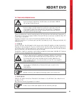
10. Operating Procedures For Parallel Systems
10.1.
Introduction
KEOR T EVO UPS Systems are designed according to high MTBF figures with increased reliability.
To increase the output power or the UPS system availability a second (or more) KEOR T EVO UPS can be
connected in parallel redundant/power. Maximum of 4 identical power KEOR T EVO unit can be connected
in parallel.
You may see the block diagrams of Parallel Systems in Appendix-6: Description of UPS and Block Diagram.
There are two paralleling modes you may choose via Front Panel.
You may reach this menu with service
password, only.
10.1.1.
Redundancy
The UPS parallel system is redundant when one or more UPS units can be stopped by failure or maintenance
operation without affecting the load supply by the remaining operating UPS units.
N+1 redundancy means than one UPS unit can be stopped without affecting secured load supply.
N+2 redundancy means than up to two UPS unit can be stopped without affecting secured load supply.
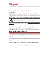
Maximum Load per parallel UPS unit to keep redundancy:
Parallel configuration must only be activated by LEGRAND UPS Technical Service
Personnel.
10.1.2.
Power Increase
If Power Increase Mode is selected, the total capacity of the system is N times the capacity of each UPS
unit. Maximum load per unit can reach 100% in normal operation. All running UPS units in parallel share
the load equally.
In case of any problem on one of the units, the remaining units may operate in overload and the loads
supplied through bypass after certain time.
Number of Parallel UPS Units
2
3
4
N+1
50%
66%
75%
N+2
...
33%
50%
Table.13
Redundanc
y
Summary of Contents for KEOR T EVO
Page 1: ...KEOR T EVO 10 15 20 KVA Installation Operation Manual LE10507AA ...
Page 2: ...LE10507AA KEOR T EVO ...
Page 24: ...22 Figure 6 3 1 3 Figure 6 3 1 4 Power Cables Path Communication Cables Path ...
Page 30: ...28 Figure 6 3 1 4 1 KEOR T EVO 10 1x24pcs 9Ah BATTERY WIRING DIAGRAM ...
Page 32: ...30 Figure 6 3 1 4 3 KEOR T EVO 10 1x24pcs 9Ah BATTERY WIRING DIAGRAM ...
Page 76: ...74 SEPARATED RECTIFIER AND BYPASS INPUTS FOR SINGLE UPS UNIT ...
Page 82: ...Notes ...
Page 83: ......


