LEGRAND 0 026 72 Manual Download Page 22

22/29

Technical data sheet: S000114123EN-1 

Updated: 

Created: 18/01/2021

Cat. No(s): 0 026 72/73/74/76/78/79

KNX controller multi-application DIN

   7 .  COMMUNICATION OBJECTS (continued)

7 .9 "Valve Control" parameter (continued)
7 .9 .2 "A – Valve General" parameter (continued)

  Valve position [0…100]%

*0

…100

This parameters are configured the blind height and slat position.

Valve contact type

*normally open

  normally closed

This parameter is used to select reaction after bus voltage recovery.

Value  control duration from 0…100% in s 

[10…6000]

  0…

*180

…6000

With this parameter, a time is set in seconds that the connected valve 

requires to move from position 0 % (valve closed) to position 100 % 

(valve fully open). If the valve control parameter is selected three point 

open/close, this parameter is visible.
For example, the time is 180s, the current valve position is at 20%, the 

target position is 60%, and then the travel time of the valve will need 

72s from 20% to 60%.

Automatically adjust valve position in s 

[10…6000]

*no

  yes

This function is mainly used to correct the valve position, for example, 

the valve is not fully opened or closed after long working hours due 

to various reasons lead to the valve position slight inaccuracies, such 

temperature, aging of the device etc. So it needs to be repositioned 

via the function. If the valve control parameter is selected three point 

open/close, this parameter is visible.

Number of valve control up to adjustment 

[1…65535]

1…

*100

…65535

This parameter is selected automatic adjustment threshold 

which automatic adjustment is undertaken. Assuming that the 

parameterized value is 100, when the number of valve controls arrived 

to 100, if the valve is adjusted to the opening direction on the 101st 

adjustment, then the automatic adjustment is not executed, if to the 

closing direction, the automatic adjustment will be executed, and 

the valve is adjusted to the position 0%, and then adjusted to the 

target position. For example, on the 100st the valve position is 50%, 

if the 101st the valve position is 60%, the valve position is adjusted 

directly to 60% and do not execute an automatic adjustment until a 

reversal control value is received. If the 101st the valve position is 40%, 

an automatic adjustment is undertaken and the valve is adjusted to 

the position 0%, and then adjusted to the target position 40%. The 

automatic adjustment is exceeded the closing position by % 5 of the 

total travel time. This time is maximum one minute.

Valve limitation

  yes

*no

The limitation of the control value limits the height of the control 

value. The limitation is activated, when a value is chosen which 

is smaller/higher than the possible value for the control value, so 

minimum larger than 0 or maximum smaller than 1.If an input signal is 

out of the adjusted limitation, it will be decreased or increased.

Example:

 At the heating mode, the maximum limit is chosen as 

70% and the minimum limit is chosen as 10%. The valve opening is 

adjusted as 10min. If a control value is sent as 100% for the input, the 

channel takes the maximum limit of 70% and calculates from this 

value the on-pulse as 7min. A control value in the limitations works 

normal, so a control value of 50% creates an on-pulse of 5min

   7 .  COMMUNICATION OBJECTS (continued)

7 .9 "Valve Control" parameter (continued)
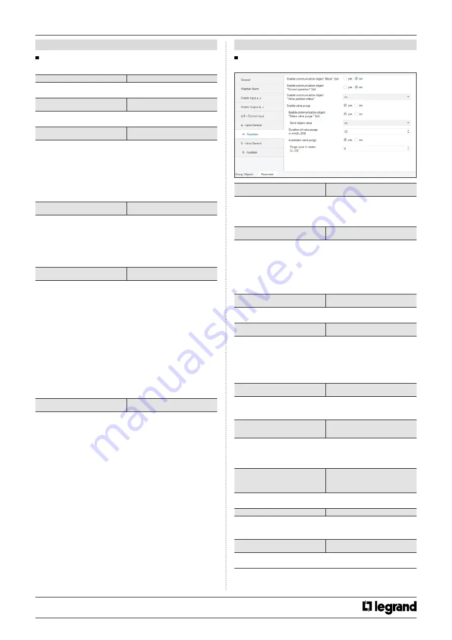
7 .9 .3 "A – Function" parameter

Enable communication object “Block” 1 bit

  yes

*no

A channel can be blocked for further operations by its blocking object. 

While valve is moving, block object is activated the valve finished its 

move.

Block on object value

*1

  0

1

: The blocking is triggered by sending a logical “

1

” at the belonging 

block object. Only through sending a logical “

0

”, the channel is 

unblocked again.

0

: The blocking is triggered by sending a logical “

0

” at the belonging 

block object. Only through sending a logical “

1

”, the channel is 

unblocked again.

Enable communication object “Forced 

operation” 1 bit

  yes

*no

The forced position drives the control value to a fixed position.

  Forced operation on obj value

*1

  0

1

: A logical “

1

” activates the forced position. By sending a logical “

0

”, 

the forced position is deactivated

0

: A logical “

1

” activates the forced position. By sending a logical “

0

”, 

the forced position is deactivated and the channel goes back to its last 

value or the last received telegram for the control value.

Value position on forced operation In % 

[0…100]

0…

*30

…100

This parameter determines the valve position after forced operation 

activates.

Enable communication object “Valve 

position status” 

*no

  1 bit

  1 byte

This parameter is select sends/responds the actual value of the valve 

percentage. The valve status object is sent as soon as possible after 

the control value is received.

Send object value

*no

  after a change

  after request

  after change or request

The parameter is selected object send type. 

Duration of valve purge In min [1…255]  

1…

*10

…255

If the valve purge is activated, the actuator opens the corresponding 

valve for a period.

Automatic valve purge

  yes

*no

Automatic control can be enabled with this parameter.

CONTENTS

Summary of Contents for 0 026 72

Page 1: ...ch Sensor parameter 10 7 5 2 a Switch Dim Sensor parameter 11 7 5 2 a Switch Dim Sensor parameter continued 11 7 5 3 a Blind Sensor parameter 11 7 5 4 a Value Forced Operation parameter 12 7 6 Enable...

Page 2: ...n parameter 23 7 10 2 A B1 Status Message parameter 24 7 10 3 A B1 Automatic Operation parameter 25 7 10 4 A B1 Direct Mode parameter 25 7 11 Function Chart 26 7 12 Object Description 26 7 12 1 Genera...

Page 3: ...ut x4 AC Blind x2 DC Blind x1 2 Point valve x2 3 point valve x2 Suitable for switching resistive capacitive and inductive loads as well as fluorescent lamp loads according to EN 60 669 A single switch...

Page 4: ...4123EN 1 Updated Created 18 01 2021 Cat No s 0 026 72 73 74 76 78 79 KNX controller multi application DIN 4 CONNECTION 0 026 72 73 AC Motor D2 NA Fan1 Fan2 Fan3 4 CONNECTION continued 0 026 74 AC Moto...

Page 5: ...ted 18 01 2021 Cat No s 0 026 72 73 74 76 78 79 KNX controller multi application DIN 4 CONNECTION continued 0 026 76 AC Motor AC Motor DC Motor F G DC Motor F G 4 CONNECTION continued 0 026 78 79 AC M...

Page 6: ...S4 or higher Important A detailed information about parameter configuration can be found in Product Manual of device Installation and commissioning of device may only be implemented by trained electri...

Page 7: ...100 1 bit CW 98 Output A1 Staircase lighting duration 7 007 2 byte CRW Output A Output A B Move to position height 0 255 5 001 1 byte CW Fan A B1 Switch speed 3 1 001 1 bit CW Control input Fault con...

Page 8: ...e sent freely within a period Note If the value of the object cannot be sent in the time of a period The object is buffered for the next period time The buffered object will be updated if the object v...

Page 9: ...valuate the transmitted scene address and switches the output to the stored scene value A scene is activated when it receives its scene number at the scene object The storing of the current channel va...

Page 10: ...is distinction between short and long operation The contact type of the push button attached to the channel is adjusted here Cyclic transmission of object no switch OFF switch ON always This paramete...

Page 11: ...operation STOP telegram sends at the end of operation Brightness change on every sent telegram 100 6 25 1 56 This parameter is only visible with the Dimming steps options This parameter is cyclically...

Page 12: ...op command is sent such as STOP Lamella adj UP or STOP Lamella adj DOWN 1 Shutter MOVE UP STOP Lamella UP 2 Shutter MOVE DOWN STOP Lamella DOWN 2 button stepping On operation Stop lamella adjustment T...

Page 13: ...n shutter blind DC fan coil valve control individually Both output group can be combined into one DC blind In DC blind operation the four relay contacts of the device can be used to control electrical...

Page 14: ...bus voltage return Behavior bus voltage failure keep position open contact close contact When the bus voltage fails the device set the wanted switching state of the output The relay can be open close...

Page 15: ...mber of pre warning and time for pre warning interval The warning function is for warning that the staircase lighting time run out and the lights are switched off soon In the warning lights short turn...

Page 16: ...B General parameter continued Behavior after ETS programming or after ETS reset Behavior bus voltage failure no reaction up down stop position 1 2 3 4 approach position This parameter can be used to c...

Page 17: ...e Trigger reference movement communication object is visible The reference movement is triggered via this communication object In long time slight inaccuracies can occur so the upper and lower end pos...

Page 18: ...This function allows you set a height position or slat position directly using with communication object Enable communication objects Move to pos Height Move slat 0 255 no yes The communication Move t...

Page 19: ...havior in case of rain alarm Behavior in case of frost alarm no reaction up down stop position 1 position 2 position 3 position 4 individual position When the alarm is activated the blind moves this p...

Page 20: ...tion communication object is updated After the bus voltage return forced position function set to the parametrized position Set the parameter to no forced position active The forced operation is deact...

Page 21: ...ING is deactivated Set the parameter to 1 When the telegram is received 1 HEATING operation is activated COOLING is deactivated Monitoring control valves yes no This parameter activate the thermostat...

Page 22: ...vel time This time is maximum one minute Valve limitation yes no The limitation of the control value limits the height of the control value The limitation is activated when a value is chosen which is...

Page 23: ...ons Thus initially the number of fan levels required for the connected devices can be defined The number of fan levels can be specified separately for each fan coil channel Controlling the fan levels...

Page 24: ...ime has elapsed 7 COMMUNICATION OBJECTS continued 7 10 Fan Coil parameter continued 7 10 2 A B1 Status Message parameter Enable communication object Status fan speed x 1 bit yes no The data format for...

Page 25: ...peed In s 0 65535 0 65535 This parameter defines the dwell time for a fan speed of the fan until it switches to the next higher or lower fan speed 0 no delay time for switching 7 COMMUNICATION OBJECTS...

Page 26: ...x Des 1 0x00 0 0x80 128 2 0x01 1 0x81 129 3 0x02 2 0x82 130 4 0x03 3 0x83 131 5 0x04 4 0x84 132 6 0x05 5 0x85 133 7 0x06 6 0x86 134 8 0x07 7 0x87 135 9 0x08 8 0x88 136 10 0x09 9 0x89 137 11 0x0A 10 0x...

Page 27: ...d operation 1 byte 0 255 DPT 5 001 brightness value 2 byte 32768 32767 DPT 7 001 signed value 2 byte 0 65535 DPT 8 001 unsigned value 4 byte float value DPT14 068 temperature 4 byte 0 4294967295 DPT12...

Page 28: ...or 4 104 Trigger reference movement Output A DTP 1 008 1 bit CW This object is triggered the reference movement If the telegram is received the blind is moved up or down end position Then the blind c...

Page 29: ...OMMUNICATION OBJECTS continued 7 17 Fan Object Description No Object name Name DTP Type Length Flags 95 Fan speed switch Fan DPT 5 010 1 byte CW This object is used to switch on fan speed via 1 byte o...

Reviews: