DWG. NO.
DATE
SHEET 1 OF 1
DO NOT SCALE DRAWING
99300978
8-22-07
L-SCREW
ARM
CROSS
CLAMP
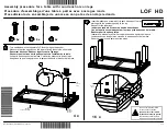
Figure 2
WOOD
SIDE RAIL
SCREW
WOOD
Figure 8
CROSS
ARM
BOLT
SIDE RAIL
METAL
ARM
CROSS
NUT
Figure7
CLAMP
CLAMP
CROSS
ARMS
CENTER
ARM
Figure 3
Q31LP ASSEMBLY INSTRUCTIONS
Figure 6
40" - 50"
APPROX.
ARM
Figure 4
ARM
CROSS
CENTER
CLAMP
1"
Figure 5
Step 1:
Tap PLASTIC INSERT into LEG. With flat
side up, screw WING NUT onto GLIDE. Thread
GLIDE into PLASTIC INSERT. See Figure 1.
Step 2:
Loosely attach L-SCREWS to CLAMPS
and slide CLAMPS onto CROSS ARMS as shown
in Figure 2.
Step 3:
Place CENTER ARM under CROSS ARMS and
slide CLAMPS onto overlapped CROSS/CENTER
ARMS as shown in Figure 3.
Step 4
: Adjust to width needed and position each
CLAMP one inch from the edge of the lower
CROSS ARM as shown in Figure 4. Tighten L-
SCREWS.
If using one cross support:
Place assembled cross support in the center of the
bed as shown in Figure 5.
If using two cross supports:
Place assembled cross supports between side rails,
approximately 40 to 50 inches apart as shown in
Figure 6.
Step 5:
Attach CROSS ARMS to SIDE RAILS. For
metal side rails use NUTS and BOLTS as shown in
Figure 7. For wood side rails use WOOD SCREWS
as shown in Figure 8.
Step 6:
Adjust GLIDES so that they touch the floor.
Tighten WING NUT against PLASTIC INSERT.
Note: There must be at least one inch of the
glide stem in the plastic insert.
Step 7:
Tighten all nuts, bolts, and L-screws.
NUT
LEG
INSERT
PLASTIC
ARM
CENTER
Figure 1
WING
GLIDE


