Shenzhen Legevo Technology Co.,Ltd.
13
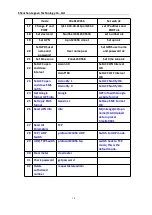
6 Digital input 2
Black
Ground wire
It can be used as a ground wire connected to an analog sensor.
Connect to an external sensor, such as the temperature sensor
7 Digital input 4
Blue
Digital input 1, negative trigger (SOS button by default)
8 Output 1
White
Valid: low level (0 V)
Invalid: open drain
Maximum voltage for output open drain (invalid): 45 V
Maximum current for output low voltage (valid): 500 mA
Connect to an external relay to remotely cut off the vehicle fuel cable or
engine power supply.
9 Output 2
Yellow
Valid: low level (0 V)
Invalid: open drain
Maximum voltage for output open drain (invalid): 45 V
Maximum current for output low voltage (valid): 500 mA
Connect to an external relay to remotely cut off the vehicle fuel cable or
engine power supply.
2.GPS Vehicle Tracker Installation
GPS tracker should be installed by technical professional of local service centre.
Without permission, the user cann’t repair and move the tracker randomly. If users do,
any unfortunated damage should be compensated by himself.
Installation steps (caution: the following installation should under no power, otherwise
will be dangerous)
1.Power supply line: The red wire connects 12V“+”;Black wire connects to
12V“-”
2. Wire for cutting off oil of the tracker
Yellow wire connects the relay pin 86; 85 pin connect to 12 V DC , 87a pin and 30 pin in
series power supply circuits. Caution: Wrong connection of yellow wire will damage the
tracker.
3. Wire for cutting off circuit of the tracker
White wire connects relay pin 86; 85 pin to 12 V DC, 87a pin and 30 pin are in series
power supply circuits. Caution: Wrong connection of yellow wire will damage the tracker.
4. Emergency triggering alarm
The blue wire connects the positive of the alarm button, and the black wire connects the
negative of the alarm button.


