INSTRUCTION MANUAL
Rio Rancho, NM, USA
www.lectrosonics.com
Fill in for your records:
Serial Number:
Purchase Date:
US Patent 7,225,135
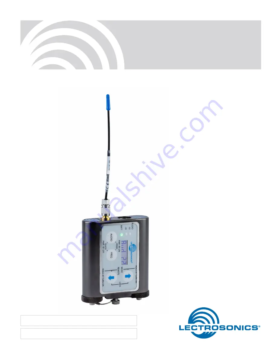
WM
Watertight Transmitter and Remote Controls
With Digital Hybrid Wireless
®
Technology
Page 1: ...TION MANUAL Rio Rancho NM USA www lectrosonics com Fill in for your records Serial Number Purchase Date US Patent 7 225 135 WM Watertight Transmitter and Remote Controls With Digital Hybrid Wireless Technology ...
Page 2: ...WM LECTROSONICS INC 2 ...
Page 3: ...rating this micro phone system without a license is subject to certain restrictions the system may not cause harmful interference it must operate at a low power level not in excess of 50 milliwatts and it has no protection from interference received from any other device Purchasers should also be aware that the FCC is currently evaluating use of wireless mi crophone systems and these rules are sub...
Page 4: ...its of conventional FM wire less systems and it does away with the analog com pandor and its artifacts General Technical Description No Pre Emphasis De Emphasis The Digital Hybrid design results in a signal to noise ratio high enough to preclude the need for conventional pre emphasis HF boost in the transmitter and de emphasis HF roll off in the receiver This eliminates the potential for distortio...
Page 5: ...optimize the transmitter for maximum battery life or for maxi mum operating range Power output is selected using the LCD in a setup mode while the RF output of the transmitter is turned off Battery Operation Switching power supplies convert battery voltages to operate various circuit stages with maximum efficiency The firmware remembers the settings when the bat teries are exhausted After new batt...
Page 6: ... prevent distortion during high peak levels It is important to set the gain audio level high enough to achieve full modulation during louder peaks in the audio The DSP controlled limiter can handle peaks over 30 dB above full modulation so with an optimum setting the LEDs will flash red during use If the LEDs never flash red the gain is too low The 20 LED turns red at 0 dB full modulation Signal L...
Page 7: ...es the O ring on the cap The spring contact on the cap maintains solid contact on the battery regardless of its exact length The O rings should be kept clean and dry and coated with petroleum jelly on a regular basis See page 11 for more information on preventing corrosion DO NOT COVER VENT HOLES About Batteries The transmitter is powered by two AA batteries Lithium batteries are recommended for l...
Page 8: ...he same location The LCD displays rf OFF to remind you that the unit is not transmitting Use the AUDIO and FREQ buttons to access the vari ous setup screens When the adjustments are com plete press both the AUDIO and FREQ buttons briefly to save the settings and turn the unit off Compatibility Output Power Bias Voltage phantom power LCD Backlight and Tuning Step Size Selector Five different setup ...
Page 9: ...LEDs indicate the audio level and limiter activity Once set the transmitter s audio level setting should not be used to control the volume of your sound system or recorder levels This gain adjustment matches the transmitter gain with the microphone s output level the user s voice level and the position of the microphone Output Power Extended operating range and increased immunity to dropouts can b...
Page 10: ...e it will be neces sary to turn the transmitter off then power it up again in normal operation so the RF output will be on Then the other components in the sound or recording system can be adjusted Frequency Selection The frequency can be displayed either in MHz or as a two digit hexadecimal number and can be set in the Standby Mode or when the transmitter is powered up in the normal operating mod...
Page 11: ...he batteries have been replaced When this function is turned off the AUDIO and FREQ buttons need to be held in for the completion of the count to turn the unit back on for normal operation This is a unique behavior that takes place only when the batteries fail during operation If the unit is turned off manually a quick press of the buttons will turn it on in the standby mode instead The firmware i...
Page 12: ... a sound system because the reflec tions and reverberation in the room will alter the tones Powering the RM on and off To turn the RM on or off press the AUDIO and FREQ buttons together briefly The unit powers up on the page that was displayed when the unit was powered off last The setup screens are accessed with the AUDIO and FREQ buttons Once on the desired screen the value is adjusted with the ...
Page 13: ...ifferent block number than the transmitter and an attempt is made to set the transmitter s frequency in MHz the command will still work The transmitter is simply set to the corresponding channel in the correct block with a matching hexadecimal number The audio signal from the RM will change the set tings of all transmitters within range Experiment with this to prevent accidental changes to another...
Page 14: ...iOS The iPhone version keeps each available setting on a separate page with the list of options for that setting On iOS the Activate toggle switch must be enabled to show the button which will then activate the audio The iOS version s default orientation is upside down but can be configured to orient right side up The purpose for this is to orient the device s speaker which is at the bottom of the...
Page 15: ...perly positioned 4 Transmitter and receiver not on same frequency Check switches display on transmitter and receiver 5 Transmitter and receiver not on same frequency block 6 Operating range is too great 7 Defective transmitter antenna NO SOUND OR LOW SOUND LEVEL RECEIVER INDICATES PROPER AUDIO MODULATION 1 Receiver output level set too low 2 Receiver output disconnected or cable defective or mis w...
Page 16: ...s a serious condition that requires factory repair It may be possible to operate on another frequency far removed from the one that was selected when the condition was indicated TRANSMITTER WON T RESPOND TO REMOTE CONTROL 1 If LCD blinks rc oFF transmitter has not been configured to respond to the remote control See Remote Control Operation on page 8 for instructions on how to configure 2 If LCD b...
Page 17: ...te lavaliere microphones for use with the WM transmitter WPMC 10 Watertight connector kit 10 piece to terminate lava liere microphones for use with the WM transmitter Replacement O rings Model ORINGKIT WM Includes replacement O rings for battery caps and microphone plug with WM style connector and petroleum jelly pouch Separate parts P N 35877 O ring 433 ID x 623 OD P N 35750 O ring 312 ID x 437 O...
Page 18: ... measuring the length of the antenna If the antenna is damaged in severe conditions and the whip is cut to a shorter length the table and template can be used to verify that the antenna is the correct length for the frequency block of the transmitter Measure the whip length from the dimensions in the table or print out this page and lay the transmitter on top of the template NOTE Be sure to verify...
Page 19: ...onsists of pre assembled battery doors with thumbscrew and hex key Allen wrench Install new battery caps and tighten the thumb screw by hand The thumbscrew is removed to recondition dry out the desiccant beads Eventually the desiccant beads absorb enough mois ture that they will become ineffective and turn green or blue instead of the normally dry color of amber orange To recharge the desiccant it...
Page 20: ...rature Replacing the desiccant beads When the beads remain darker green or blue they may not be absorbent any longer and should be replaced Remove the screw that retains the spring and vented cover with a small Phillips screwdriver While the cap assembly is apart and the beads re moved the parts can be cleaned to remove dust and corrosion The best way to clean the parts is with petro leum jelly Va...
Page 21: ...anel mounted membrane switches Modulation indicators Dual bicolor LEDs indicate modulation of 20 10 0 10 dB referenced to full modulation Controls Control panel with LCD and four membrane switches Low frequency roll off Adjustable from 35 to 150 Hz 30 100 1kHz 10k 20k 6 3 0dB 3 6 9 12 Line in Mic in 150 Hz Roll off Mic in 35 Hz Roll off Audio Frequency Response 35 Hz to 20 kHz 1 dB The low frequen...
Page 22: ...e complies with FCC radiation exposure limits as set forth for an uncontrolled environment This device should be installed and operated so that its antenna s are not co located or operating in conjunction with any other antenna or transmitter This device complies with Industry Canada radiation exposure limits as set forth for a controlled professional use only The FCC requires that the following s...
Page 23: ...epairs Returning Units for Repair For timely service please follow the steps below A DO NOT return equipment to the factory for repair without first contacting us by email or by phone We need to know the nature of the problem the model number and the serial number of the equipment We also need a phone number where you can be reached 8 A M to 4 P M U S Mountain Standard Time B After receiving your ...
Page 24: ...Lectrosonics Inc will pay for the cost of returning your equipment to you This warranty applies only to items returned to Lectrosonics Inc or an authorized dealer shipping costs prepaid within one year from the date of purchase This Limited Warranty is governed by the laws of the State of New Mexico It states the entire liablility of Lectrosonics Inc and the entire remedy of the purchaser for any ...