PP011-1
X
PP011-2
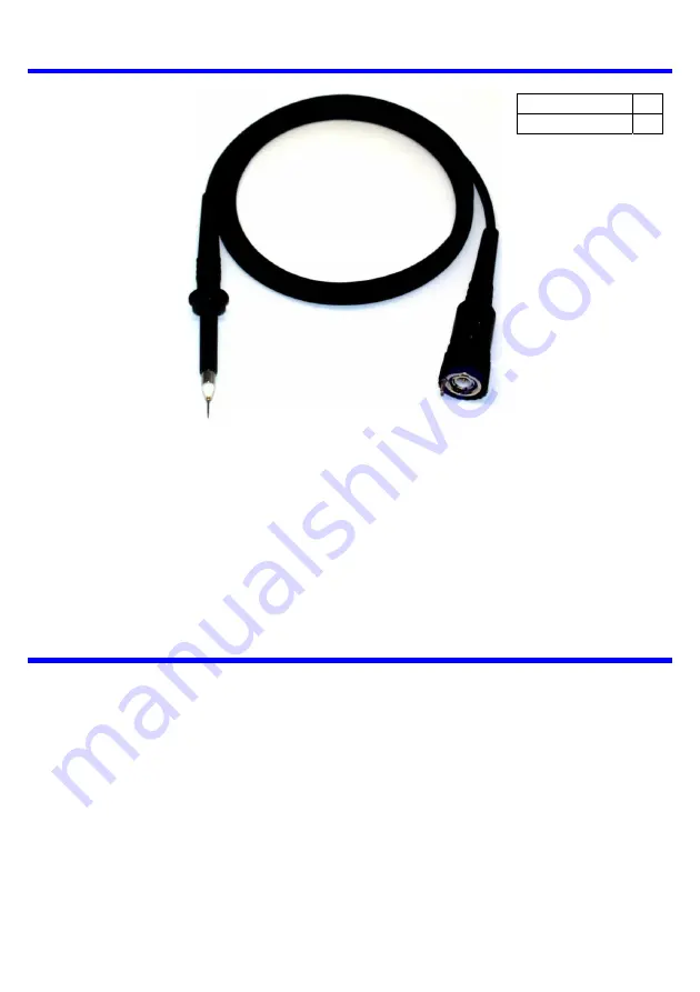
LeCroy PP011 Passive Probe
Instruction Manual
Revision A – October 2006
Page 1: ...PP011 1 X PP011 2 LeCroy PP011 Passive Probe Instruction Manual Revision A October 2006 ...
Page 2: ...imited to any implied warranty of merchantability fitness or adequacy for any particular purposes or use LeCroy shall not be liable for any special incidental or consequential damages whether in contract or otherwise Corporate Headquarters 700 Chestnut Ridge Road Chestnut Ridge NY 10977 6499 Tel 845 425 2000 Fax 845 425 8967 Internet www lecroy com 2006 by LeCroy Corp All rights reserved LeCroy Ac...
Page 3: ...cuit Do not connect the probe ground terminal to any point in the test circuit which is at a potential other than earth ground Do not apply any potential to the input which exceeds the maximum ratings of the probe Comply with the voltage derating curve When measuring high frequency signals be sure to comply with the Voltage vs Frequency derating curve found on page 5 Do not use in wet or explosive...
Page 4: ...ion Range 10 20 pF Bandwidth 500 MHz 3 dB Electrical Ratings Maximum Input Voltage Measurement category I 400 Vrms 1250 V transient overvoltage see voltage derating curve on page 5 Measurement category II 300 Vrms CAT II Pollution Degree 2 Measurement category I is for measurement performed on circuits not directly connected to a mains supply Measurement category II CAT II is for measurement perfo...
Page 5: ... 5 Certifications This probe is designed to conform to 73 23 EEC amendment 93 68 EEC Low Voltage Directive LVD per the following standards CEI IEC 61010 031 2002 01 Safety requirements for electrical equipment for measurement control and laboratory use Part 031 Safety requirements for hand held probe assemblies for electrical measurement and test Frequency Hz 100 K 1 M 10 M 0 VIN Vrms 50 150 250 3...
Page 6: ...elated to specific application needs The PK005A series of connectivity accessories are compatible with any LeCroy 5 mm PP011 series probe Accessories are shown with the LeCroy part number followed by the description Standard Accessories PK1 5MM 101 PK1 5MM 102 PK1 5MM 103 Sprung Hook Standard Ground Lead Adjustment Tool PK1 5MM 104 PK1 5MM 105 PK1 5MM 106 Rigid Tip 0 8 mm Insulating Cap Color Codi...
Page 7: ...IC Cap 2 54 mm pitch Ground Spring Input Adapters and Clips PK1 5MM 111 PK1 5MM 112 PK1 5MM 116 PK1 5MM 117 Single Lead Adapter Dual Lead Adapter Adapter 2 mm plug Adapter 4 mm plug PK1 5MM 113 PK1 5MM 114Y PK1 5MM 115Y Pico Hook PK1 5MM 114G PK1 5MM 115G Micro Clip Long Micro Clip Short PP011 OM E Rev A 7 ...
Page 8: ...t which eliminates the need to hand hold the probe Probe connected using PCB Adapter PC Board hole size and pattern K1 5MM 107 Use of PCB Adapter The PCB adapter LeCroy P N PK1 5MM 107 is intended to be designed into and permanently installed i provide a reliabl 1 5 mm 0 059 1 0 mm x 4 0 039 5 8 mm 0 200 8 PP011 OM E Rev A ...
Page 9: ... Lead with 8 mm socket Ground Lead with 2 mm plug PK1 5MM 122 PK1 5MM 123 Ground lead with 4 mm plug High Frequency Compensated Ground Lead The PK1 5MM 123 High Frequency compensated ground lead allows operation with long ground lead with minimum signal distortion PP011 OM E Rev A 9 ...
Page 10: ...of PK1 5MM 115Y PK1 5MM 115G PK1 5MM 114Y PK1 5MM 114G PK1 5MM 111 Use and Maintenance This probe is a high quality precision instrument To maintain accuracy and signal fidelity mechanical shock should be avoided as well as damage to the cable through excessive bending Avoid placing excessive force sideways on the tip Should the tip become damaged it may be replaced by the user using the procedure...
Page 11: ... is performed by connecting the input of the probe to a low frequency square wave such as the oscilloscope calibrator signal set to 1 kHz The compensation is adjusted by rotating the adjustment accessible through the small hole in the center of the housing near the BNC connector Use the tool supplied with the probe for this adjustment Undershoot Overshoot Correct adjustment Should HF compensation ...
Page 12: ...o change the tip or replace it when damaged carefully grip the outer most portion of tip and pull straight out along the axis of the probe using needle nose pliers Do not attempt to grip the plastic insulator with pliers when removing the tip as this will squeeze the tip which will make it difficult or impossible to remove Do not grip the outer gold plated tube which the tip slides into With the t...