PP007-WR-1
PP007-WR-2
PP007-WS-1
PP007-WS-2…
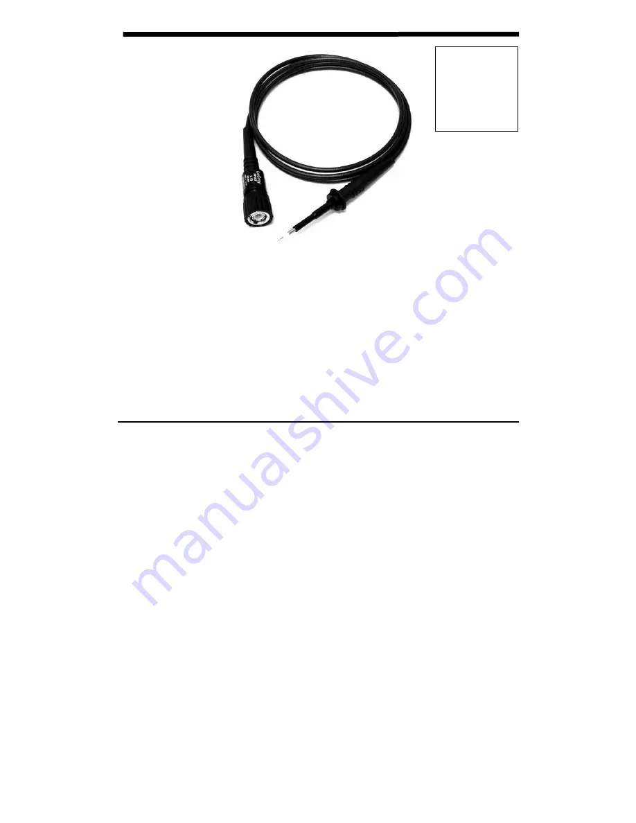
Instruction Manual LeCroy PP007-WR / PP007-WS Passive Probe
Revision D – July 2004
Page 1: ...PP007 WR 1 PP007 WR 2 PP007 WS 1 PP007 WS 2 Instruction Manual LeCroy PP007 WR PP007 WS Passive Probe Revision D July 2004 ...
Page 2: ...e for the transportation and insurance charges for the return of products to the service facility LeCroy will return all products under warranty with transportation charges prepaid This warranty replaces all other warranties expressed or implied including but not limited to any implied warranty of merchantability fitness or adequacy for any particular purposes or use LeCroy shall not be liable for...
Page 3: ...circuit Do not connect the probe ground terminal to any point in the test circuit which is at a potential other than earth ground Do not apply any potential to the input which exceeds the maximum ratings of the probe Comply with the voltage derating curve When measuring high frequency signals be sure to comply with the voltage versus frequency derating curve found on page 8 Do not use in wet or ex...
Page 4: ...cations Electrical Characteristics Attenuation 10 1 Input Resistance 10 MΩ 1 Input Capacitance 9 5 pF Input Impedance see plot on page 5 Compensation Range 10 20 pF Bandwidth 500 MHz 3 dB Electrical Ratings Maximum Input Voltage Measurement category I 400 V rms 1250 V transient overvoltage see voltage derating curve on page 5 Measurement category II 300 V rms CAT II Pollution Degree 2 Measurement ...
Page 5: ...ications 100 200 300 350 250 150 50 VIN Vrms 400 100 M 1 M 100 K 0 Frequency Hz 10 M 100 M 1 k Frequency Hz 1 M 100 1 k 10 k 1 M 100 k ZIN Ω 10 M 10 This probe is designed to conform to 73 23 EEC amendment 93 68 EEC Low Voltage Directive LVD per the following standards CEI IEC 61010 031 2002 01 Safety requirements for electrical equipment for measurement control and laboratory use Part 031 Safety ...
Page 6: ...of connectivity accessories are compatible with any LeCroy 2 5 mm PP0x7 series probe Accessories are shown with the LeCroy part number followed by the description Standard Accessories 1 2 3 PK007 001 PK007 002 PK007 003 Sprung Hook Standard Ground Lead Adjustment Tool 4 5 6 7 8 9 10 11 PK007 004 Rigid Tip 0 5 mm PK007 007 PK007 008 IC Cap 0 5 mm pitch green PK007 005 Spring Tip 0 5 mm Insulating C...
Page 7: ...OM E PCB Adapter Instruction Manual 7 Use of PCB Adapter The PCB adapter LeCroy P N PK007 015 is intended to be designed into and permanently installed in circuit boards to provide a reliable high frequency test point which eliminates the need to hand hold the probe 1 5 mm 0 059 5 8 mm 0 200 1 0 mm x 4 0 039 Probe connected using PCB Adapter PC Board hole size and pattern ...
Page 8: ...K007 017 PK007 018 PK007 022 PK007 023 Single Lead Adapter Dual Lead Adapter Adapter 2 mm plug Adapter 4 mm plug 21 22 23 PK007 019 PK007 020 PK007 021 Pico Hook Micro Clip Long Micro Clip Short 24 PK007 031 BNC Adapter For low voltage use only 42 V pk AC DC 8 ...
Page 9: ...0 PK007 026 PK007 027 PK007 028 Ground Llead with mini clip Ground Lead with 8 mm socket Ground Lead with 2 mm plug 31 32 PK007 029 PK007 030 Ground lead with 4 mm plug High Frequency Compensated Ground Lead The PK007 030 High Frequency compenated ground lead allows operation with long ground lead wiith minimum signal distortion ...
Page 10: ...04 Micro Clip Kit adapts the probe for use with 0 5 mm IC lead clips It contains 1 each of designators 16 17 18 and two of each micro clip designators 22 and 23 Use and Maintenance This probe is a high quality precision instrument To maintain accuracy and signal fidelity mechanical shock should be avoided as well as damage to the cable through excessive bending To achieve the small 2 5 mm tip size...
Page 11: ...nsation is performed by connecting the input of the probe to a low frequency square wave such as the oscilloscope calibrator signal set to 1 kHz The compensation is adjusted by rotating the adjustment accessible through the small hole in the center of the housing near the BNC connector Use the tool supplied with the probe for this adjustment Undershoot Overshoot Correct adjustment Should HF compen...
Page 12: ...To change the or replace it when damaged carefully grip the outer most portion of tip and pull straight out along the axis of the probe using needle nose pliers Do not attempt to grip the plastic insulator with pliers when removing the tip as this will squeeze the tip which will make it difficult or impossible to remove Do not grip the outer gold plated tube which the tip slides into With the tip ...