EM882S Digital Stepper Drive User Manual
Motion Control Products Ltd. Tel.: (+44) 01202 599922
2.4 Elimination of Heat
⚫
EM882S
’s working temperature is less than 60
℃
(140°F)
⚫
It is recommended to use automatic idle-current mode to reduce motor heating. That means set the SW4 pin of
DIP switch at “OFF” position.
⚫
It is recommended to mount the drive vertically to maximize heat sink area. Use forced cooling method to cool if
necessary.
3. Connection Pin Assignments and LED Indication
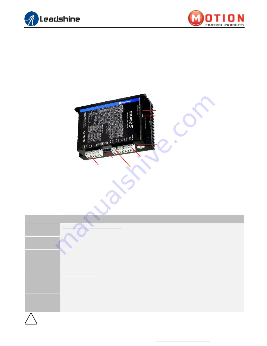
S1:DIP Switch
P3:Motor and Power
Supply Connector
P2:Fault Outputs
P1:Control Signal Inputs
Status LEDs
S2: Rotation Switch
Selector 2
P4:Tuning Port
Figure 2
Connectors, DIP switches, and LED locations
The EM882S has 4 connectors P1, P2, P3 and P4, 2 DIP switch S1 and rotation switch S2. P1 is for control signal
connections, P2 is for fault output, P3 is for motor and power connection, P4 is for fine tuning.
3.1 P1 - Control Connector Configurations
PIN
Details
PUL+ (CW+)
Pulse and Direction Connection:
(1)
Optically isolated, high level 4.5-5V, low voltage 0-0.5V
(2)
Maximum 200 KHz input frequency
(3)
The width of PUL signal is at least 2.5
μs
, duty cycle is recommended 50%
(4)
Single pulse (step & direction) or double pulse (CW/CCW) is set by Leadshine ProTuner
(5)
DIR signal requires advance PUL signal minimum 5
μs
in single pulse mode
(6)
The voltage of control signal is 5V, need to connect a 2K resistance when it is 24V
PUL- (CW-)
DIR+ (CCW+)
DIR- (CCW-)
ENA+
Enable Connection: Optional.
(1)
Optically isolated, differential.
(2)
Disable the drive by 4.5-5.0V input connection; enable the drive by 0-0.5V connection(default
no connection)
(3)
ENA signal requires advance DIR signal minimum 5
μs
in single pulse mode
(4)
Enable time to be at least 200ms
ENA-
!
Notice
Notes:
(1) shield cables are required for P1
; (2) don’t tie
P1/P2 cables and P3/P4 cables together.


