


CS-D1008E Closed Loop Stepper Drive User Manual
Page | 9
5.1 Regulated or Unregulated Power Supply
The CS-D1008E can power medium and large size stepping motors (frame size from NEMA 23 to 34). To get good
driving performances, it is important to select supply voltage and output current properly. Generally speaking, supply
voltage determines the high speed performance of the motor, while output current determines the output torque of the
driven motor (particularly at lower speed). Higher supply voltage will allow higher motor speed to be achieved, at the
price of more noise and heating. If the motion speed requirement is low, it’s better to use lower supply voltage to
decrease noise, heating and improve reliability.
5.2 Power Supply Sharing
Multiple CS-D1008E drives can share one power supply to save space and reduce cost, if that power supply has
enough power capacity. To avoid cross interference, connect each stepper drive directly to the shared power supply
separately. To avoid cross interference, DO NOT daisy-chain connect the power supply input pins of the Drivers.
Instead connect them to power supply separately.
5.3 Selecting Supply Voltage
The CS-D1008E is designed to operate within 18-80VAC or 24-110 VDC voltage input. When selecting a power
supply, besides voltage from the power supply power line voltage fluctuation and back EMF voltage generated during
motor deceleration needs also to be taken into account. Ideally it is suggested to use a power supply with the output of
30-90VDC or 20-70VAC, leaving room for power line voltage fluctuation and back-EMF.
If using an AC transformer,
be sure to use a transformer with isolation. Otherwise there is a risk of electrocution.
6. DIP Switch Configurations
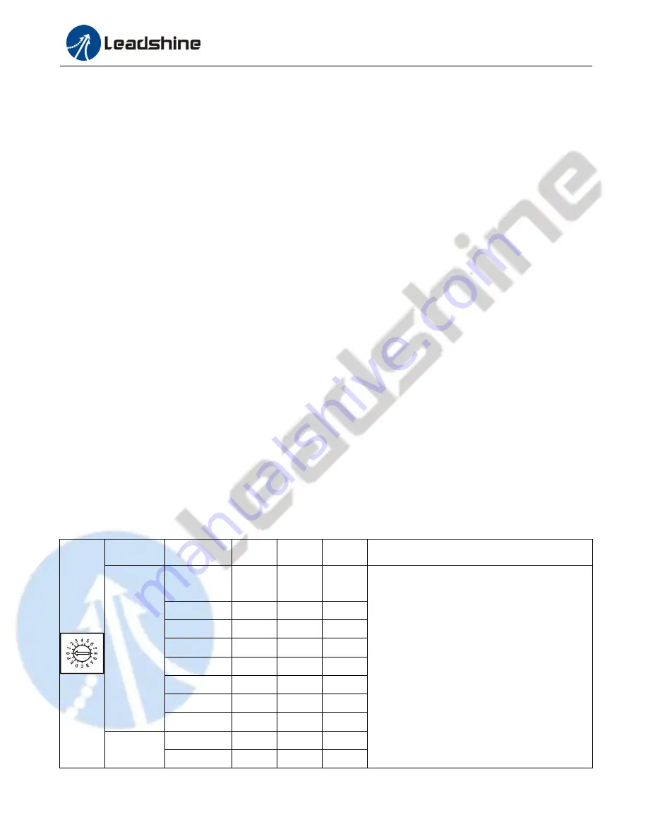
6.1 S1 - Rotating Switch Configurations
This rotating switch is used to set the peak current of the drive and motion gain, from the motor phase current and
application requirements.
Peak
Current
Code
Velocity
loop Ki
Position
loop Kp
Velocity
loop Kp
Remark
8.0 A
(Actual
output
current
fluctuates
from 4-8A
following
the load)
0 (factory and
default)
0
25
25
1) Velocity loop Ki indicates the stop time and
position accuracy, “0” indicates the stop time is
short, but the position error is slightly larger. “16”
means the stop time is long, but the position error
is smaller. As usual “0” meets most applications.
2) Position loop Kp and velocity loop Kp is a pair
of composite parameters that represent stiffness.
“25” and “25” composite parameters indicate the
stiffness is weak, “100” and “5” composite
parameters indicate the rigidity is strong.
Sometimes if the motor will rotate after stopping,
it can increase the value of position loop Kp, but
if the value is too large, the motor will have noise.
1
0
50
15
2
0
75
10
3
0
100
5
4
16
25
25
5
16
50
15
6
16
75
10
7
16
100
5
6.0 A
(Actual
8
0
25
25
9
0
50
15