background image

4. BEFORE YOU BEGIN MEASURING 

33


4.8 

Menu Display 

You can configure various settings in the setup menus, but the setup menus are not 
displayed all of the time. To display a setup menu, you can either hold down the appropriate 
key for 0.5 seconds or more,(*1) or you can use the function keys or function dials on the 
appropriate display.(*2) 


Setup menus automatically disappear after 10 seconds of user inactivity. To change this 
display time, follow the procedure in section 5.8, “Setting the Menu Display Time.” 
Regardless of the display time setting, the input menu, system menu, preset registration 
menu, and preset menu do not disappear because of user inactivity. 


*1 

The top-level setup menu appears. You do not need to hold down the keys to display the input menu, 
system menu, screen capture menu, preset menu, or display mode preset menu. 

*2 

The level of the setup menu that was displayed most recently appears. 


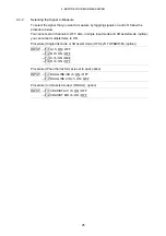
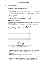
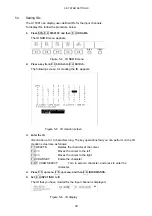
As an example, if you do not perform any operations for 10 seconds in the situation shown 
below, the picture menu will disappear. 


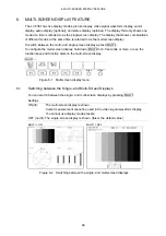
Figure 4-10    Displaying setup menus 1 


 Hold Down a Display Mode Key to Display Its Menu 

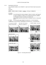
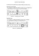
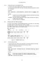
If you hold down PIC after the picture menu has disappeared, the top level of the picture 
menu appears. 


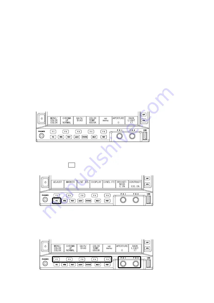
Figure 4-11    Displaying setup menus 2 


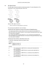
 Using the Function Keys to Display a Menu 

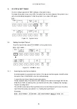
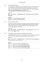
If you use the function keys or the function dials after the picture menu has disappeared, 
the picture menu will reappear at the level that it was at before. 


Figure 4-12    Displaying setup menus 3 

Summary of Contents for LV 5381

Page 1: ...LV 5381 MULTI SDI MONITOR LV 5381SER01 DUAL LINK LV 5381SER02 AUDIO LISSAJOUS DISPLAY LV 5381SER03 STATUS DISPLAY LV 5381SER04 3D ASSIST LV 5381 OP70 REMOTE TALLY INSTRUCTION MANUAL ...

Page 2: ...1 Video Signal Formats and Standards 6 2 3 2 Audio Playback 6 2 3 3 Input Output Connectors 7 2 3 4 Control Connectors 8 2 3 5 LCD 9 2 3 6 Screen Capture 9 2 3 7 Preset Settings 9 2 3 8 Main Display Features 10 2 3 9 Video Signal Waveform Display 10 2 3 10 Vector Display 11 2 3 11 5 Bar Display 12 2 3 12 Picture Display 12 2 3 13 CINELITE Display 13 2 3 14 Embedded Audio Display Option 14 2 3 15 E...

Page 3: ...Setting the Auto Shutoff Time 38 5 2 2 Adjusting the Backlight 38 5 3 Setting IDs 39 5 4 Configuring the Display 40 5 4 1 Setting the Time Code Display Format 40 5 4 2 Displaying Error Counters and the Time 40 5 4 3 Displaying the Input Format 40 5 4 4 Setting the Input Channel Display Format 41 5 5 Configuring Remote Settings Option 41 5 5 1 Selecting Remote Mode 41 5 5 2 Selecting the Alarm Pola...

Page 4: ...ay 58 8 2 Saving Screen Capture Data 59 8 3 Displaying Screen Capture Data 60 8 4 Displaying Screen Capture Data Saved to USB Memory 60 9 PICTURE DISPLAY 61 9 1 Picture Display Explanation 61 9 2 Setting the Brightness and Contrast 62 9 2 1 Setting the Brightness 62 9 2 2 Setting the Contrast 62 9 3 Adjusting the Picture 63 9 3 1 Switching between the Color and Monochrome Displays 63 9 3 2 Amplify...

Page 5: ...f Stop Screen Explanation 80 9 7 2 Procedure for Displaying the f Stop Screen 81 9 7 3 DISPLAY Screen Explanation 82 9 7 4 Setting Measurement Points 84 9 7 5 Selecting the Measurement Size 84 9 7 6 Configuring User Defined Correction Tables 84 9 7 7 Displaying Synchronized Markers 89 9 7 8 Configuring Line and Sample Numbers 91 9 8 Configuring CINEZONE Settings 91 9 8 1 Gradation Display 91 9 8 2...

Page 6: ...114 11 4 4 Selecting the Fixed Gain 116 11 4 5 Setting the Variable Gain 116 11 5 Configuring Line Selection and Sync Signal Settings 117 11 5 1 Turning Line Selection On and Off 117 11 5 2 Selecting Lines 118 11 5 3 Setting the Line Selection Range 118 11 5 4 Switching the Sync Signal 118 11 6 Configuring Display Settings 119 11 6 1 Selecting the Display Format 120 11 6 2 Displaying the Luminance...

Page 7: ...he Display Format 140 12 6 2 Selecting the Setup Level 141 12 6 3 Displaying a Scale for 75 Intensity Color Bars 141 12 7 Configuring the 5 Bar Display 142 12 7 1 5 Bar Display Explanation 142 12 7 2 Setting the Display Order 143 12 7 3 Selecting the Scale Unit 144 13 AUDIO DISPLAY 145 13 1 Standard and Optional Features 145 13 2 Audio Display Explanation 146 13 3 Setting the Input Channels 147 13...

Page 8: ...9 14 5 2 Setting the User Reference of the Phase Difference 171 14 5 3 Setting the Phase Difference to the Default Value 171 14 5 4 Measuring Phase Differences between Channels 172 14 5 5 Measuring the Phase Difference between Links A and B 172 14 5 6 Switching the Sync Signal 172 14 6 Configuring Video Error Settings 173 14 6 1 Detecting CRC Errors 173 14 6 2 Detecting EDH Errors 173 14 7 Configu...

Page 9: ... 1 1 Picture Menu 16 186 16 1 2 Video Signal Waveform Menu 16 191 16 1 3 Vector Menu 16 194 16 1 4 Audio Menu Option 16 196 16 1 5 Status Menu Option 16 197 16 1 6 Multi Screen Display Menu 16 199 16 1 7 Preset Registration Menu 16 200 16 1 8 Input Menu 16 201 16 1 9 Screen Capture Menu 16 201 16 1 10 System Menu 16 202 16 2 Change History of the Software 16 204 Index ...

Page 10: ...stand If you have any questions about the contents of this manual please contact your local LEADER agent Symbols and Terms The following symbols and terms are used in this instruction manual and on the instrument to indicate important warnings and notes Symbol This symbol appears in this instruction manual and on the instrument to indicate an area where improper handling could result in personal i...

Page 11: ... the power cord is damaged stop using it and contact your local LEADER agent Using a damaged power cord could lead to electrical shock or fire When removing the plug from the power outlet do not pull on the cord Pull from the plug Installation Environment Operating Temperature Range Use this instrument in a 0 to 40 C environment Using the instrument with its vents blocked or in a high temperature ...

Page 12: ... instrument for an extended period of time remove the power plug from the outlet Do Not Insert Foreign Materials If foreign materials such as metal flammable objects or liquid are allowed into the instrument through the vents for example fire electric shock damage to the instrument or some other accident may result If You Notice Something Wrong during Operation If you notice smoke fire a strange s...

Page 13: ...ild detergent and wipe gently While cleaning make sure that foreign materials such as water and detergent do not enter the instrument If liquid or a metal object enters into the instrument fire or electric shock may result About the European WEEE Directive This instrument and its accessories are subject to the European WEEE Directive Follow the applicable regulations of your country or region when...

Page 14: ...iod 1 Repair of malfunction or damages resulting from fire natural calamity or improper voltage applied by the user 2 Repair of an instrument that has been improperly repaired adjusted or modified by personnel other than a factory trained LEADER representative 3 Repair of malfunctions or damages resulting from improper use 4 Repair of malfunctions caused by devices other than this instrument 5 Rep...

Page 15: ...g Up To ensure more accurate measurements turn on the instrument approximately 30 minutes before you intend to use it to allow its internal temperature to stabilize 1 2 6 Backup Battery If the backup battery runs out the LV 5381 exhibits the following behavior If this happens contact your local LEADER agent The last memory feature is disabled The clock is initialized The contents of all presets ar...

Page 16: ...display it also has a rich assortment of other display features such as a picture display audio level meter display 5 bar display transmission error detection and gamut error detection Wide Variety of Display Formats In the video signal waveform display vector display and picture display the LV 5381 can display up to four input SDI signals on top of each other or side by side This makes it suitabl...

Page 17: ...ignal Input The LV 5381 can receive a tri level sync signal or an NTSC or PAL black burst signal as its external sync signal and then display video signal waveforms with this sync signal as its reference Preset Feature Up to 30 sets of panel settings can be registered as presets and loaded easily at a later time Registration of settings that are used repeatedly can help you work more efficiently I...

Page 18: ...o lissajous option enables the LV 5381 to display the lissajous curves and the numeric values of levels of the audio that is embedded in an SDI signal Status Option LV 5381SER03 The addition of the status option enables the LV 5381 to show analysis displays such as the data dump phase difference and event log displays 3D Assist Option LV 5381SER04 The addition of the 3D assist option enables the e...

Page 19: ...s 1080i 60 59 94 50 1080p 30 29 97 25 24 23 98 1080PsF 30 29 97 25 24 23 98 RGB 4 4 4 12 bits 1080i 60 59 94 50 10 bits 1080p 60 59 94 50 1080p 30 29 97 25 24 23 98 1080PsF 30 29 97 25 24 23 98 YCBCR 4 2 2 12 bits 1080i 60 59 94 50 SMPTE 372 1920 1080 1080p 24 23 98 RGB 4 4 4 2K 12 bits 1080PsF 24 23 98 2048 1080 When Set to Single Link Format Switching Manual automatic When Set to Dual Link When ...

Page 20: ... Output Voltage 800 mVp p 10 Output Return Loss 15 dB for 5 MHz to the serial clock frequency External Sync Input 1 Input Signal Tri level sync or NTSC PAL black burst signal Input Connectors Two BNC connectors Input Impedance 15 kΩ passive loop through Input Return Loss 30 dB for 50 kHz to 30 MHz into 75 Ω Maximum Input Voltage 5 V DC peak AC Headphone Output Output Signal Extracts and transmits ...

Page 21: ...scription Recall of preset data not possible for function presets Remote Mode BIT BINARY Number of Loadable Presets 30 in BINARY mode or 8 in BIT mode Input Channel Switching Description Selection of the input signal to display Single Input Mode Select channel A channel B channel C or channel D Simultaneous Input Mode Turn channel A channel B channel C and channel D on and off 3D Assist Mode when ...

Page 22: ...re Screen Capture Captures the screen to an image file only one screen capture is stored in internal memory Media Internal memory RAM and USB memory Data Output Screen captures can be saved as bitmap files to USB memory Data Input Data saved to USB memory can be loaded and displayed on the LV 5381 2 3 7 Preset Settings Preset Mode Comprehensive preset display mode preset Comprehensive Presets Save...

Page 23: ...ay can be turned on and off Two Screen Display Splits the display into two screens left and right Four Screen Display Splits the display into four screens User Layout User Layout Displays the user defined layout Number of User Layouts Four two for single input mode and two for simultaneous input mode 2 3 9 Video Signal Waveform Display Simultaneous Input Mode Display Format Mixed tiled aligned Wav...

Page 24: ...ement Displayed in usec or msec Frequency Display Computes and displays the frequency with the length of one period set to the time between two cursors Scale Type scale V scale decimal scale hexadecimal scale Display Color 7 colors User Marker Display Type mV or Number of Markers 1 or 2 Thumbnail Display Picture audio level meter 2 3 10 Vector Display Simultaneous Input Mode Display Format Mixed t...

Page 25: ...Temperature 6500 K 9300 K Image Quality Adjustment Brightness contrast chroma gain RGB gain RGB bias aperture Display Sizes Fit full frame real 4 3 full screen Color Selection R G B can be turned off separately Chroma off Frame Rate The frame rate is converted and displayed using the internal sync signal Aspect Marker HD SDI 4 3 13 9 14 9 2 39 1 SD SDI 13 9 14 9 16 9 Aspect Marker Format Line shad...

Page 26: ...isplay Synchronizes the markers on the vector display or waveform display to the measurement points of the CINELITE display s f Stop display or display Vector Marker Display Displays numerically the specified position on the vector display Number of Markers Synchronized Marker Up to 4 Vector Marker 1 Vector Numeric Display Displays numerically the active marker position Cb Displays the CB position...

Page 27: ...two groups from groups 1 2 3 and 4 Simultaneous Input Mode One AES EBU pair per input channel 2 3 15 Error Count Display Function Used to count the video audio and gamut errors Video Error Display Counts CRC HD SDI and EDH SD SDI errors Audio Error Display Counts embedded audio BCH HD SDI and channel status bit CRC errors Gamut Error Display Counts gamut composite gamut and luminance errors Low Pa...

Page 28: ... are converted to composite signals Luminance Error Detects level errors in the luminance component Event Log Recorded Events Errors changes in input type time stamps etc Recording Capacity Up to 1000 events Operation Records all events from start to finish Data Output Saved in text format to USB memory Data Dump Operation Mode Run hold Data Array Single Link Mode Serial component Dual Link Mode L...

Page 29: ...s added to the difference between the monochrome video signal for the left eye and the monochrome video signal for the right eye Overlay Display The levels of the video signal for the left eye and the video signal for the right eye are halved These signals are then combined Checker Display Displays the video signal for the left eye and the video signal for the right eye in a checkerboard pattern B...

Page 30: ...Display Format Side by side overlayed Wipe Feature L R wipe Disparity Measurement Feature Description Position the cursor at a point in the picture to measure the disparity and luminance level at that point Alarm If the upper limit is exceeded NG no good is displayed Measurable Items Screen disparity dots cm perceived depth m angle of vergence Time Code Description The time codes for the video sig...

Page 31: ...the selected key is lit more brightly Power Switch Stores whether the instrument is on or off Last Memory Backs up the panel settings to memory 2 3 20 General Specifications Environmental Conditions Operating Temperature Range 0 to 40 C Operating Humidity Range 85 RH or less no condensation Optimal Temperature 10 to 30 C Power Supply Voltage 10 to 18 VDC Power Consumption 46 W max Dimensions 215 W...

Page 32: ...3 NAMES AND FUNCTIONS OF PARTS 19 3 NAMES AND FUNCTIONS OF PARTS 3 1 Front Panel Figure 3 1 Front panel ...

Page 33: ... key option Press Shows the status display Shows the display mode preset menu 1 Hold down Shows the status menu Chapter 14 8 MULTI key Press Switches between the single and multi screen displays Hold down Shows the multi screen display menu Chapter 6 9 PSET key Press Shows the preset menu Hold down Shows the preset registration menu Chapter 7 10 INPUT key Switches the input channel 4 3 11 CAP key ...

Page 34: ...t connectors 4 5 18 INPUT SDI A INPUT SDI B INPUT SDI C INPUT SDI D SDI signal input connectors 4 2 19 OUTPUT SDI A B OUTPUT SDI C D Reclocked SDI signal output connectors 4 4 20 DC INPUT DC inlet 4 1 21 Serial number label The serial number is printed here 22 REMOTE option Remote control connector Used to load presets transmit the alarm signal and perform other operations 5 5 15 1 ...

Page 35: ...er switch on the front panel The power switch s LED lights when the power is on When you turn on the power the LV 5381 starts with the same panel settings that were being used when it was last turned off However the following items are cleared the error counter LAPSED the status screen s error counts optional the event log optional and the capture data 4 1 3 Turning the Power Off To turn off the p...

Page 36: ...es single input mode in which the LV 5381 measures a single signal that is applied to one of its input connectors and simultaneous input mode and 3D assist mode option in which the LV 5381 simultaneously measures multiple signals that are applied to its input connectors To switch between the input modes press INPUT on the front panel When you are using simultaneous input mode or 3D assist mode L R...

Page 37: ...multiple input connectors simultaneously SIMUL The input mode is set to single The LV 5381 measures the signal applied to one of its input connectors 3D ASIST The input mode is set to 3D assist mode The video signal for the left eye and the video signal for the right eye are displayed simultaneously 3D assist mode is an option the LV 5381SER04 which is sold separately INPUT MODE SINGLE INPUT MODE ...

Page 38: ...nput mode and 3D assist mode option you cannot set multiple items to ON Procedure Single link mode or 3D assist mode HF SbyS TOP BOTM option INPUT F 1 A ch ON OFF F 2 B ch ON OFF F 3 C ch ON OFF F 4 D ch ON OFF Procedure When the link format is set to dual option INPUT F 1 DUALLINK A B ch ON OFF F 3 DUALLINK C D ch ON OFF Procedure In 3D assist mode L R DUAL option INPUT F 1 3D ASIST A C ch ON OFF...

Page 39: ... and measured Likewise the 3D signals of channels B and D can be measured Apply signals that are the same format to channels A and C or to channels B and D HF SbyS The side by side signal applied to channel A B C or D is measured TOP BOTM The top and bottom signal applied to channel A B C or D is measured Video signal for the left eye Video signal for the right eye 3D INPUT FORMAT L R DUAL channel...

Page 40: ... has been output up to that point is maintained The currently selected input signal channel C or D is reclocked and transmitted from OUTPUT SDI C D If you select channel A or B the state of the signal that has been output up to that point is maintained Single input mode dual link or simultaneous input mode To select the output signal follow the procedure below Procedure INPUT F D 1 OUT A B A B F D...

Page 41: ...al or an NTSC PAL black burst signal to the external reference input connectors Figure 4 7 External sync signal input connectors Loop Through As shown in the figure below the external sync signal input connectors are loop through Apply the input signal to one of the two connectors and terminate the other connector at 75 Ω or connect it to another 75 Ω device If you connect to another device be sur...

Page 42: ...4 1 External sync signal formats Input Signal Format 525i 59 94 625i 50 1080i 60 1080i 59 94 1080i 50 1080PsF 30 1080PsF 29 97 1080PsF 25 1080PsF 24 1080PsF 23 98 1080p 30 1080p 29 97 1080p 25 1080p 24 1080p 23 98 720p 60 720p 59 94 720p 50 720p 30 720p 29 97 720p 25 720p 24 720p 23 98 NTSC with 10 Field IDs 59 94 Hz NTSC 59 94Hz PAL 50Hz 1080i 60 1080i 59 94 1080i 50 1080PsF 30 1080PsF 29 97 1080...

Page 43: ...play Explanation This section explains the common items in all measurement displays by using the picture display as an example Depending on the measurement display some of these items may not be displayed Figure 4 9 General display explanation 1 Input Format The input signal format appears here You can also choose to hide this information See sections 5 1 Setting the Input Format and 5 4 3 Display...

Page 44: ...h the operating environment contact your local LEADER agent 5 Key Lock Indication This symbol appears when the key lock is enabled See section 4 6 Enabling the Key Lock 6 USB Indication This symbol appears when USB memory is connected to the LV 5381 7 Error Counter In single input mode when the single screen display is in use the error counters current time and elapsed time appear here You can als...

Page 45: ...al waveform display The contents of the thumbnail display vary as shown below depending on the selected display mode With some exceptions you can also choose to hide this information Table 4 2 Thumbnail display Thumbnail Display Display Mode Audio Meter Picture Video Signal Waveform Histogram Notes PIC 1 2 See section 9 6 5 Setting the Thumbnail Display WFM X See section 11 6 9 Setting the Thumbna...

Page 46: ...inactivity 1 The top level setup menu appears You do not need to hold down the keys to display the input menu system menu screen capture menu preset menu or display mode preset menu 2 The level of the setup menu that was displayed most recently appears As an example if you do not perform any operations for 10 seconds in the situation shown below the picture menu will disappear Figure 4 10 Displayi...

Page 47: ...example to set F 4 COLOR TEMP in the figure below press F 4 Pop up commands appear You can select a command by pressing F 4 Figure 4 13 Selecting pop up commands Specifying Values As an example to set F D 1 APERTURE in the figure below turn F D 1 If you press F D 1 this setting is set to its default value of 0 Figure 4 14 Specifying values ...

Page 48: ...nk Format Option Dual link signals are supported as an option To measure dual link signals install the dual link option the LV 5381SER01 which is sold separately To select the link format follow the procedure below It takes approximately 20 seconds to switch between the dual link and single link formats While the LV 5381 is switching from one link format to the other it displays the message System...

Page 49: ...ECT AUTO MANUAL Settings AUTO The input format is detected automatically MANUAL The input format must be set manually 5 1 3 Selecting i or PsF When the link format is set to single even if you set F 2 FORMAT SELECT to AUTO the following input formats cannot be detected automatically 1080i 60 and 1080PsF 30 1080i 59 94 and 1080PsF 29 97 1080i 50 and 1080PsF 25 To select whether to display the input...

Page 50: ...default value 50 30 29 97 25 24 23 98 525i 59 94 SINGLE 625i 50 1080i default value GBR10bit default value GBR12bit YC12bit 1080PsF GBR10bit default value GBR12bit YC12bit DUAL 1080p GBR10bit default value GBR12bit YC10bit YC12bit 1080PsF GBR12bit 2K 1080p default value GBR12bit When the link format is set to dual the field and frame frequencies are set automatically 5 1 5 Selecting the Composite ...

Page 51: ...utomatically 5sec The backlight is shut off after 5 seconds of user inactivity 5min The backlight is shut off after 5 minutes of user inactivity 30min The backlight is shut off after 30 minutes of user inactivity 5 2 2 Adjusting the Backlight To adjust the backlight brightness follow the procedure below The larger the number the brighter the backlight Press F D 1 to set the brightness to the defau...

Page 52: ...D creation screen 3 Enter the ID IDs can be up to 10 characters long The key operations that you can perform on the ID creation screen are as follows F 1 DELETE Deletes the character at the cursor F 2 Moves the cursor to the left F 3 Moves the cursor to the right F 4 CHAR SET Enters the character F D 1 CHAR SELECT Turn to select a character and press to enter the character 4 Press F 5 up menu F 5 ...

Page 53: ... of the status display Procedure SYS F 2 DISPLAY F 4 INFORMATION F 1 TIME CODE LTC VITC OFF Settings LTC The LTC time code embedded in the input signal is displayed VITC The VITC time code embedded in the input signal is displayed OFF No time codes are displayed 5 4 2 Displaying Error Counters and the Time To select whether to display the error counters VIDEO_ERR AUDIO_ERR and GAMUT_ERR and time T...

Page 54: ...ption To configure remote settings press F 1 REMOTE SETUP on the system menu This setting is available when the remote and tally option OP70 is installed The settings that you make here will not be reset to their default values even if you initialize the LV 5381 In addition they are not recorded to presets SYS F 3 I F SETUP Figure 5 8 REMOTE SETUP menu 5 5 1 Selecting Remote Mode To select remote ...

Page 55: ...re below If you select CH A B an alarm is generated whenever an error occurs on either channel A or channel B If you select CH C D an alarm is generated whenever an error occurs on either channel C or channel D Procedure SYS F 3 I F SETUP F 1 REMOTE SETUP F 3 ALARM SELECT CH A CH B CH C CH D CH A B CH C D 5 5 4 Selecting the Function to Assign to the Remote Control Connector When F 1 REMOTE MODE i...

Page 56: ...mory Procedure 1 SYS F 4 DATE TIME F 1 DATE 2 F 1 YEAR F D 1 DATE SET To set the year 3 F 2 MONTH F D 1 DATE SET To set the month 4 F 3 DAY F D 1 DATE SET To set the day 5 F 4 COMPLETE To confirm the date setting 5 6 2 Setting the Time To set the time follow the procedure below The time you set appears in the upper left of the screen next to TIME It is also used when various kinds of data are save...

Page 57: ...tically disappear if OFF is selected Press F D 1 to reset the setting to its default value 10 seconds Regardless of the display time setting the input menu system menu preset registration menu and preset menu do not disappear because of user inactivity Procedure SYS F 5 next menu F 2 MENU AUTO OFF F D 1 TIME SET 5 sec 10 sec 60 sec OFF 5 9 Configuring License Settings 5 9 1 Installing Options To u...

Page 58: ...d its corresponding option becomes usable The name of the option that has been added appears in the LICENSE LIST FAILED appears if the license key is not correct Enter an appropriate number To remove an installed option enter the license key and then press F 4 REMOVE 5 9 2 Viewing the MAC Address and Installed Options Use the license display to view the MAC address of the LV 5381 and the options t...

Page 59: ...displays press MULTI To configure the multi screen display hold down MULTI for 0 5 seconds or more or use the function keys and function dials on the multi screen display MULTI Figure 6 1 Multi screen display menu 6 1 Switching between the Single and Multi Screen Displays You can switch between the single and multi screen displays by pressing MULTI Settings ON lit The multi screen display is shown...

Page 60: ... is the default setting for 3D assist mode MULTI MODE DUAL MULTI MODE QUAD Figure 6 3 Selecting the display format 6 3 Selecting the Display Area When F 1 MULTI MODE is set to DUAL or QUAD to assign display modes to the different areas of the screen follow the procedure below You cannot assign the same display mode to multiple areas You cannot select AUDIO and STATUS if the audio and status option...

Page 61: ... signals for the left and right eyes can be displayed separately VEC PIC The pictures are shown side by side and the vector display is shown below them If 3D INPUT FORMAT is set to L R DUAL vectors are displayed on top of each other Channels A and B the video signals for the left eye are displayed in red and channels C and D the video signals for the right eye are displayed in cyan LAYOUT SELECT W...

Page 62: ...e Press F D 1 to move the boundary line to the center of the screen For information on the SIMUL MODE setting see section 11 6 8 Selecting the Display Format of Simultaneous Input Mode Procedure MULTI F 4 WFM WIPE ON OFF Settings ON The displays of channel A or B the video signal for the left eye and channel C or D the video signal for the right eye are separated at the border Channel A or B is di...

Page 63: ...the USB memory device to the LV 5381 To cancel the copy operation press F 3 COPY NO 4 Set F 1 MULTI MODE to USER 5 Press F 2 USER LAYOUT to select the layout to display You can select the user layout from SINGLE1 SINGLE2 SIMUL1 and SIMUL2 SINGLE represents the single input mode and SIMUL represents the simultaneous input mode 6 7 2 Copying All User Layouts To copy all the user layouts from the LV ...

Page 64: ... from the preset menu Display Mode Presets You can register up to five different sets of panel settings for each display mode 2 When you load a display mode preset the settings of other display modes and the input channels are not affected This feature cannot be used with the multi screen display Registering Display Mode Presets Set the LV 5381 to the settings that you want to register and then ho...

Page 65: ... that you want to register 2 Hold down PSET The preset registration menu appears Figure 7 1 Preset registration menu 3 Press F 1 FULL PRESET The file list screen appears Figure 7 2 File list screen 4 Press F 2 COMMENT INPUT The file name input screen appears Figure 7 3 File name input screen ...

Page 66: ...er of the file you want to register 7 Press F 3 STORE If a file has already been stored with the file number that you selected an overwrite confirmation prompt appears If you want to overwrite the current file press F 1 OVER WR YES Otherwise press F 3 OVER WR NO 7 1 2 Loading Presets 1 Press PSET The preset menu appears Figure 7 4 Preset menu 2 Press a function key from F 1 No 1 to F 5 No 5 If the...

Page 67: ...letes the character at the cursor F 2 Moves the cursor to the left F 3 Moves the cursor to the right F 4 CHAR SET Enters the character F D 1 CHAR SELECT Turn to select a character and press to enter the character After you enter the file name press F 5 up menu You can also copy the file name of an already registered file To copy a file name move the cursor to the file in the file list whose name y...

Page 68: ... preset menu 5 Press a function key from F 1 No 1 to F 5 No 5 7 2 3 Deleting Display Mode Presets 1 Press the key of the display mode whose preset you want to delete 2 Hold down PSET The preset registration menu appears 3 Press F 2 FUNCTION PRESET The file list screen appears This setting does not appear when the multi screen display is in use 4 Turn F D 1 FILE SELECT to select the file number of ...

Page 69: ...o the LV 5381 to USB memory follow the procedure below If presets have already been saved to the USB memory they will be overwritten To cancel the copy operation press F 3 COPY NO The file structure in the USB memory is shown below Note that the file numbers in the USB memory are different from the LV 5381 file numbers by one If you change the file names on the USB memory device you will not be ab...

Page 70: ...USB memory as a BMP file See section 8 2 Saving Screen Capture Data Save the screen capture to USB memory as a BSQ file See section 8 2 Saving Screen Capture Data Display the screen capture on the LV 5381 See section 8 3 Displaying Screen Capture Data View the screen capture file on a PC See section 8 2 Saving Screen Capture Data Display the screen capture on the LV 5381 See section 8 4 Displaying...

Page 71: ...enu appears You can also capture a display by pressing F 1 REFRESH on the screen capture menu The screen capture menu will disappear if a certain period of time passes with no user activity To use the menu to make a setting press one of the function keys from F 1 to F 5 The screen capture menu appears again Note that the captured data will be cleared if after capturing a display you Change the dis...

Page 72: ...le formats that you can select are explained below Set one of these formats to ON Both of the formats are set to ON by default BMP FILE The captured data is saved to the USB memory as a bitmap file You can view the saved files on a PC BSQ FILE The captured data is saved to the USB memory as a BSQ file You can view the saved data on the LV 5381 After you have finished setting the file formats press...

Page 73: ...iles See section 8 2 Saving Screen Capture Data 1 In 3D assist mode option the waveform color selected in the video signal waveform menu or vector waveform menu is used 8 4 Displaying Screen Capture Data Saved to USB Memory The data that you save in BSQ format by following the procedure in section 8 2 Saving Screen Capture Data can be displayed on the LV 5381 or it can be overlaid on the LV 5381 s...

Page 74: ... On and Off 2 Center Marker You can display a marker in the center of the picture that is 10 its size See section 9 4 2 Turning the Display of the Center Marker On and Off 3 Aspect Marker You can display a marker for the selected aspect ratio using a shadow a black space or a line See sections 9 4 3 Displaying the Aspect Marker and 9 4 4 Setting the Aspect Marker 4 Safe Action Marker You can displ...

Page 75: ...al waveform You can also turn each of these displays off See section 9 6 5 Setting the Thumbnail Display 9 2 Setting the Brightness and Contrast You can set the picture brightness and contrast by using F D 1 BRIGHTNESS and F D 2 CONTRAST on the picture menu F D 1 BRIGHTNESS and F D 2 CONTRAST appear in other levels of the picture menu as well and function in the same way PIC Figure 9 2 Picture men...

Page 76: ... F 1 ADJUST F 1 MONO COLOR COLOR MONO 9 3 2 Amplifying the Chroma Gain To switch between the two chroma gain settings follow the procedure below Procedure PIC F 1 ADJUST F 2 CHROMA UP NORMAL UP Settings NORMAL The chroma gain is the value that has been set using F 4 CHROMA GAIN UP The chroma gain is set to 2 200 0 F 4 CHROMA GAIN is not displayed 9 3 3 Turning the RGB Signals On and Off To turn th...

Page 77: ...ill be set to its default value of 0 0 Procedure PIC F 1 ADJUST F 3 GAIN BIAS F 1 R SIGNAL When set to ON F D 2 R BIAS 50 0 0 0 50 0 F 2 G SIGNAL When set to ON F D 2 G BIAS 50 0 0 0 50 0 F 3 B SIGNAL When set to ON F D 2 B BIAS 50 0 0 0 50 0 9 3 6 Setting the Chroma Gain To set the chroma gain follow the procedure below If you press F D 1 the setting will be set to its default value of 100 0 When...

Page 78: ... Adjusting the Backlight To adjust the backlight brightness follow the procedure below The larger the number the brighter the backlight If you press F D 2 the setting will be set to its default value of 17 You can also adjust the backlight brightness in the system setup by following the procedure described in section 5 2 2 Adjusting the Backlight Changing one of these values will also change the o...

Page 79: ...r information on the SIZE setting see section 9 6 1 Selecting the Display Size PIC F 2 MARKER Figure 9 5 MARKER menu 9 4 1 Turning the Display of the Frame Marker On and Off To turn the display of the frame marker on and off follow the procedure below The frame marker is displayed around the outer edge of the picture Procedure PIC F 2 MARKER F 1 FRAME ON OFF FRAME OFF FRAME ON Figure 9 6 Turning t...

Page 80: ...dure below There are three kinds of aspect markers line shadow and black The aspect marker type can be set using F D 1 SHADOW Procedure PIC F 2 MARKER F 3 ASPECT OFF 16 9 14 9 13 9 4 3 2 39 1 Settings OFF An aspect marker is not displayed 16 9 A 16 9 aspect marker is displayed This option cannot be selected when the input signal is HD 14 9 A 14 9 aspect marker is displayed 13 9 A 13 9 aspect marke...

Page 81: ... ASPECT is set to any value other than OFF Procedure PIC F 2 MARKER F D 1 SHADOW 0 50 100 Settings 0 The aspect marker is indicated with a line 1 to 99 The area around the aspect marker is indicated with a shadow 100 The area outside the aspect marker is indicated with black space SHADOW 0 SHADOW 50 SHADOW 100 Figure 9 9 Setting the aspect marker ...

Page 82: ... STANDARD SMPTE Figure 9 10 Safety markers When an aspect marker is displayed safe action and safe title markers are displayed inside the aspect marker with the aspect marker assumed to be 100 9 4 6 Turning the Display of the Safe Action Marker On and Off To turn the display of the safe action marker on and off follow the procedure below This setting is available when F 1 STANDARD is set to ARIB o...

Page 83: ...he picture or the size of the aspect marker if the aspect marker is displayed There are two types of user markers You can set their horizontal H and vertical V sizes separately Setting User Marker 1 Procedure PIC F 2 MARKER F 4 SAFETY ZONE F 2 USER ZONE1 When set to ON F D 1 USER ZONE1 H 0 90 100 F D 2 USER ZONE1 V 0 90 100 Setting User Marker 2 Procedure PIC F 2 MARKER F 4 SAFETY ZONE F 3 USER ZO...

Page 84: ...t Mode PIC F 3 LINE SEL Figure 9 12 LINE SEL menu 9 5 1 Turning Line Selection On and Off To display a marker on the selected line follow the procedure below Changing this setting will also change the video signal waveform display and vector display line selection settings Procedure PIC F 3 LINE SEL F 1 LINE SELECT CINELITE ON OFF Settings CINELITE The selected line of the line select feature is s...

Page 85: ...dure PIC F 3 LINE SEL F D 1 LINE VARIABLE 9 5 3 Setting the Line Selection Range To set the line selection range follow the procedure below This setting is available when F 1 LINE SELECT is set to ON and the input signal is interlaced or segmented frame Changing this setting will also change the video signal waveform display and vector display line selection ranges Procedure PIC F 3 LINE SEL F 2 F...

Page 86: ...9 PICTURE DISPLAY 73 9 6 Configuring Display Settings To configure the display settings press F 4 DISPLAY on the picture menu PIC F 4 DISPLAY Figure 9 14 DISPLAY menu ...

Page 87: ... This setting cannot be selected when D_LINK FORMAT is set to YC10bit X2 A single sample of the video signal is displayed with four pixels two horizontal and two vertical pixels on the screen The marker and line select features cannot be used You can adjust the picture position by using H POS and V POS This setting cannot be selected when D_LINK FORMAT is set to YC10bit X4 A single sample of the v...

Page 88: ...RM SIZE FUL SCRN Figure 9 15 Selecting the display size 9 6 2 Adjusting the Display Position To set the picture display position follow the procedure below This setting is available when F 1 SIZE is set to REAL X2 or X4 Procedure PIC F 4 DISPLAY F D 1 H POS F D 2 V POS ...

Page 89: ...Settings Procedure PIC F 4 DISPLAY F 2 GAMUT ERR DISP OFF WHITE RED MESH Settings OFF Gamut errors are not displayed WHITE The picture intensity is halved and gamut error locations are marked in white RED The picture intensity is halved and gamut error locations are marked in red MESH Gamut error locations are filled with a mesh pattern GAMUT ERR DISP OFF GAMUT ERR DISP WHITE GAMUT ERR DISP RED GA...

Page 90: ...and histogram on and off separately follow the procedure below This setting does not appear in the multi screen display or during disparity measurement in 3D assist mode option The thumbnail display of the audio meter cannot be shown in 3D assist mode Also the histogram cannot be displayed at the same time as other thumbnails Procedure PIC F 4 DISPLAY F 4 THUMBNAIL F 1 AUDIO METER ON OFF F 2 WFM O...

Page 91: ...n top of each other WFM FORM ALIGN WFM FORM MIX Figure 9 19 Selecting the video signal waveform display format 9 6 7 Selecting the Histogram Display Format When F 3 HISTGRM is set to ON to select the display format follow the procedure below Procedure PIC F 4 DISPLAY F 4 THUMBNAIL F 4 HISTGRM SETUP F 1 HISTGRM FORM LUMA PARADE OVERLAY Settings LUMA The histogram of the Y luminance signal is displa...

Page 92: ...g Which Channels to Display in the Histogram Option When F 3 HISTGRM is set to ON in 3D assist mode L R DUAL to set the channels that are displayed in the histogram follow the procedure below Procedure PIC F 4 DISPLAY F 4 THUMBNAIL F 4 HISTGRM SETUP F 2 L R SELECT LEFT RIGHT L R Settings LEFT Channel A or B the video signal for the left eye is displayed RIGHT Channel C or D the video signal for th...

Page 93: ...is not available in simultaneous input mode or 3D assist mode option or when SIZE is set to an option other than FIT 9 7 1 f Stop Screen Explanation To display the f Stop screen follow the procedure below Procedure PIC F 5 CINELITE F 1 CINELITE DISPLAY to select f Stop On the f Stop screen luminance levels are displayed using f stop exposure values The measured f Stop value for a group of measured...

Page 94: ...ve to the luminance level of 18 gray chart Include an 18 gray chart with the objects that you are filming 1 Press PIC 2 Press F 5 CINELITE 3 Press F 1 CINELITE DISPLAY and select DISPLAY 4 Press F 2 DISPLAY SETUP 5 Press F 3 UNIT SELECT and select Y The luminance levels at the cursor are displayed as percentages The measured values of cursors that are within the blanking interval are not displayed...

Page 95: ...o each cursor You can set up to three measurement points 9 7 3 DISPLAY Screen Explanation To display the DISPLAY screen follow the procedure below Procedure PIC F 5 CINELITE F 1 CINELITE DISPLAY to select DISPLAY On the DISPLAY screen you can display luminance levels as Y percentages RGB percentages or using 255 RGB levels Use F 3 UNIT SELECT to select the display format The measured values are ty...

Page 96: ...e order is R G and then B Figure 9 23 RGB display RGB 255 Display Each R G and B level is indicated using 256 steps from 0 to 255 The levels are also indicated using bars on the left side of the display the order is R G and then B The value of an RGB level that is 100 or greater is 255 The value of an RGB level that is 0 or less is 0 Figure 9 24 RGB 255 display ...

Page 97: ...P2 P3 9 7 5 Selecting the Measurement Size To select the measurement size follow the procedure below This setting is applied to P1 to P3 and REF The measurement size settings made on the menus accessed by pressing F 2 f Stop SETUP and F 2 DISPLAY SETUP are the same Procedure PIC F 5 CINELITE F 2 f Stop SETUP F 2 MEAS SIZE 1X1 3X3 9X9 F 2 DISPLAY SETUP F 2 MEAS SIZE 1X1 3X3 9X9 9 7 6 Configuring Us...

Page 98: ... F 5 up menu 3 Press F 1 CINELITE DISPLAY and select f Stop 4 Press F 2 f Stop SETUP 5 Press F 4 next menu 6 Press F 1 GAMMA and select USER1 In this example the table for USER1 is created but the tables for USER2 and USER3 can also be created in the same way 7 Press F 2 GAMMA CAL When you press F 2 GAMMA CAL a user defined correction table appears in the bottom left of the screen and the luminanc...

Page 99: ...on of the 18 gray chart Also make sure that the Lev value for f Stop values 22 0 to 2 0 increases linearly The REF value in the user defined correction table is entered when you press F 3 18 REF SET on the f Stop display For example if you use the left hand table shown below and press F 3 18 REF SET when the luminance value at the intersection of the cursors is 416 10 bit value the f Stop value at...

Page 100: ...ent Comment Comment Comment Data Data Data Data Data Data Comment When you create a correction table make sure that it conforms to the specifications listed below Overall File Specifications File Type ASCII text file Extension CLT End of Line Character CR LF Number of Lines 5000 or less Number of Characters per Line 255 or less including CR LF File Name Length 20 characters or less excluding the e...

Page 101: ...om 0 to 4095 12 bits increasing the value by one for each line A luminance level of 100 is defined as 940 10 bits 4 3760 12 bits A luminance level of 0 is defined as 64 10 bits 4 256 12 bits Separator Enter a single tab code Output Value Enter a value from 0 to 65535 16 bits 2 Save the user defined correction table to USB memory and connect the USB memory to the LV 5381 Save the correction table i...

Page 102: ...e you can select it by pressing F 1 GAMMA on the CINELITE menu A loaded correction table is displayed using the name determined by its NAME keyword 9 7 7 Displaying Synchronized Markers To synchronize the markers on the vector display and video signal waveform display to measurement points P1 to P3 and REF that you specify on the CINELITE display follow the procedure below Markers cannot be displa...

Page 103: ...e vector display Measured values are displayed using the following references Cb at position B 100 0 and Cr at position R 100 0 The distance from the center is expressed as d and hue is expressed as deg Normally markers P1 to P3 are displayed in light blue and REF in red When they fall outside the display they blink in red If this occurs OVER appears above the measured values Figure 9 28 Marker de...

Page 104: ...d displayed Use the following menu to configure these features PIC F 5 CINELITE F 1 CINELITE DISPLAY to select CINEZONE Single screen display MULTI F 3 MULTI MENU F 1 MULTI PIC F 4 DISPLAY F 4 CINELITE F 1 CINELITE DISPLAY to select CINEZONE Multi screen display This feature is not supported by and does not appear in 3D assist mode option 9 8 1 Gradation Display To display picture luminance levels...

Page 105: ... Step Display To display picture luminance levels in steps follow the procedure below On the step display luminance levels are divided into 10 steps and assigned to 12 different colors For information about F D 1 UPPER and F D 2 LOWER see section 9 8 1 Gradation Display Procedure PIC F 5 CINELITE F 2 CINEZONE SETUP F 1 DISPLAY and select STEP F D 1 UPPER F D 2 LOWER DISPLAY GRADATE DISPLAY STEP Fi...

Page 106: ...e and levels less than equal to the specified range are displayed using black To set the level that is displayed with gradation follow the procedure below The range specified by F D 2 RANGE in reference to F D 1 LEVEL is displayed with gradation Procedure PIC F 5 CINELITE F 2 CINEZONE SETUP F 1 DISPLAY and select SEARCH F D 1 LEVEL 7 3 50 0 109 4 F D 2 RANGE 0 5 12 0 100 0 DISPLAY SEARCH Figure 9 ...

Page 107: ... the Display Format Procedure PIC F 5 3D FUNCTION F 1 PICTURE FORM AGLPH CL AGLPH MO CNVRGNCE OVERLAY CHECKER WIPE FLICKER Settings AGLPH CL Green and blue are masked from the video signal for the left eye and red is masked from the video signal for the right eye These signals are then combined and displayed AGLPH MO Green and blue are masked from the monochrome video signal for the left eye and r...

Page 108: ... right eye appears to the lower right of the border You can move the border freely This is useful when you are matching the video level of two cameras FLICKER The left eye video signal and the right eye video signal are displayed on a time sharing display PICTURE FORM AGLPH CL AGLPH MO PICTURE FORM CNVRGNCE PICTURE FORM OVERLAY PICTURE FORM CHECKER 1 PICTURE FORM WIPE 1 PICTURE FORM FLICKER Figure...

Page 109: ... settings PIC F 5 3D FUNCTION Figure 10 4 3D FUNCTION menu 10 3 1 Turning the Boundary Lines On and Off To turn the boundary lines on and off follow the procedure below Procedure PIC F 5 3D FUNCTION F 3 WIPE MARKER OFF ON 10 3 2 Moving Boundary Lines To move the boundary lines follow the procedure below Press F D 1 to move the left right boundary line to the middle of the screen Press F D 2 to mov...

Page 110: ...rted vertically and video signal waveforms are inverted horizontally 2 1 When 3D INPUT FORMAT is set to HF SbyS or TOP BOTM the menu items change to F 1 LEFT and F 2 RIGHT 2 Horizontal inversion of the video signal waveform occurs only during the video period The video is not inverted in 3D assist mode HF SbyS or TOP BOTM 10 5 Selecting the Measurement Mode In the single screen display when F 1 PI...

Page 111: ...e procedure below The reference grid lines for both the disparity and horizontal grid lines are displayed in yellow Procedure PIC F 5 3D FUNCTION F 4 GRID SETUP F 1 GRID DISPLAY DISPRTY HORIZONT BOTH Settings DISPRTY Vertical grid lines are displayed Use this option when you want to perform disparity measurements HORIZONT Horizontal grid lines are displayed Use this option when you want to match t...

Page 112: ... set to HORIZONT 1 The selectable range varies depending on the input signal The values shown here are for a 1080i 59 94 input signal 10 6 4 Selecting the Grid Line Adjustment Unit To select the grid adjustment unit follow the procedure below Procedure PIC F 5 3D FUNCTION F 4 GRID SETUP F 3 GRID UNIT PIX LINE Settings PIX LINE The disparity grid lines are adjusted with pixels as the unit The horiz...

Page 113: ...tings WHITE The grid lines are displayed in white BLACK The grid lines are displayed in black GRAY1 The grid lines are displayed in dark gray GRAY2 The grid lines are displayed in light gray 10 7 Configuring Disparity Measurement Settings When F 3 MEASURE SELECT is set to DISPRTY press F 4 DISPRTY SETUP to measure disparity 10 7 1 Disparity Measurement Display Explanation Figure 10 8 Disparity mea...

Page 114: ...left eye and the video signal for the right eye are displayed 6 Upper Limit This displays the upper disparity limits that were set on the PARAMETER display Depending on the cursor position these switch automatically between the Far upper limits and the Near upper limits 7 Result When at least one measured value exceeds its upper limit this displays NG in red When all measured values are less than ...

Page 115: ...T DISPLAY Option 102 About the Names of Settings and Measurement Items The names of the settings and measurement items that are used with the LV 5381 are shown below Figure 10 9 Setting and measurement item names ...

Page 116: ...ing range 2 0 to 20 0 cm The default setting is 6 5 cm Viewing Distance Enter the distance from the screen to the viewer Setting range 0 1 to 99 9 m The default setting is 2 5 m Screen Width Enter the screen width Setting range 0 1 to 250 0 m The default setting is 1 5 m 3 Under Upper Limit enter the upper limits for the measured values If at least one measured value exceeds its limit that you ent...

Page 117: ...IGHT POS to match the R cursor with the video signal for the right eye The measured disparity is displayed at the bottom of the screen Press F D 2 to move the cursor to approximately the center of the screen To Move the V Cursor It is useful to use the V cursor when you match the positions of the L and R cursors To move the V cursor set F 2 CURSOR SELECT to V TRACK and then turn F D 1 VERT POS Pre...

Page 118: ... You can set the gain to a value between 0 2 and 10 by setting GAIN MAG and GAIN VARIABLE For information on the GAIN MAG setting see section 11 4 4 Selecting the Fixed Gain For information on the GAIN VARIABLE setting see section 11 4 5 Setting the Variable Gain 2 Selected Line The waveform of the selected line is displayed See sections 11 5 1 Turning Line Selection On and Off and 11 5 2 Selectin...

Page 119: ...ings 11 2 Setting the Display Position To set the display position use F D 1 H POS and F D 2 V POS on the video signal waveform menu These settings appear on other levels of the video signal waveform menu as well and function in the same way WFM Figure 11 2 Video signal waveform menu 11 2 1 Setting the Horizontal Position To set the video signal waveform horizontal position follow the procedure be...

Page 120: ... information on the COLOR MATRIX setting see section 11 6 1 Selecting the Display Format For information on the composite display format see section 5 1 5 Selecting the Composite Display Format Procedure WFM F 1 INTEN SCALE F 1 SCALE UNIT HDV SD HDV SDV HD SD 150 1023 3FF Settings HDV SD The scale unit is set to V for HD signals and for SD signals This value cannot be selected when SIMUL MODE is s...

Page 121: ...NIT HD SD SCALE UNIT 150 SCALE UNIT 1023 SCALE UNIT 3FF Figure 11 4 Selecting the scale unit 11 3 2 Selecting the Scale Color To select the scale color follow the procedure below Procedure WFM F 1 INTEN SCALE F 2 SCALE COLOR WHITE YELLOW CYAN GREEN MAGENTA RED BLUE ...

Page 122: ...s displayed on the multi screen display Procedure Single screen display WFM F 1 INTEN SCALE F 3 WFM COLOR F 1 WFM Ach COLOR WHITE YELLOW CYAN GREEN MAGENTA RED BLUE F 2 WFM Bch COLOR WHITE YELLOW CYAN GREEN MAGENTA RED BLUE F 3 WFM Cch COLOR WHITE YELLOW CYAN GREEN MAGENTA RED BLUE F 4 WFM Dch COLOR WHITE YELLOW CYAN GREEN MAGENTA RED BLUE Procedure Multi screen display F 2 MULTI WFM F 1 INTEN SCA...

Page 123: ...ngle screen display WFM F 1 INTEN SCALE F 3 WFM COLOR F D 2 WFM CONTRAST MONOTONE LOW MIDDLE HIGH Procedure Multi screen display F 2 MULTI WFM F 1 INTEN SCALE F 3 WFM VECT COLOR F D 2 WFM VECT CONTRAST MONOTONE LOW MIDDLE HIGH 11 3 5 Displaying Markers for 75 Intensity Color Bars To configure marker settings press F 3 MARKER on the video signal waveform menu WFM F 1 INTEN SCALE F 4 MARKER Figure 1...

Page 124: ... Settings SINGLE Marker 1 is displayed DUAL Marker 1 and Marker 2 are displayed OFF Markers are not displayed USER MARKER DUAL Figure 11 8 Displaying user markers 11 3 7 Adjusting the Waveform Intensity To adjust the video signal waveform intensity follow the procedure below When the multi screen display is in use vectors are displayed with the same intensity as the waveforms If you press F D 1 th...

Page 125: ...rade displays 11 4 2 Selecting the Sweep Method To select the video signal waveform sweep method follow the procedure below The sweep methods that you can select vary depending on the F 1 MODE setting and the input format The field and frame displays are not available in simultaneous input mode and 3D assist mode L R DUAL option For information on simultaneous input mode and 3D assist mode see sec...

Page 126: ...nd the parade display mode is being used When the input signal is interlaced or segmented frame and MODE is set to OVERLAY Settings H_1H Single lines are displayed H_2H Two lines are displayed at a time V_F1 Field 1 is displayed V_F2 Field 2 is displayed V_2V Single frames are displayed SWEEP H_1H single line display SWEEP H_2H double line display LINE SELECT ON SWEEP V_F1 field 1 display SWEEP V_...

Page 127: ...gressive and MODE is set to OVERLAY Settings H_1H Single lines are displayed H_2H Two lines are displayed at a time V Single frames are displayed SWEEP H_1H single line display SWEEP H_2H double line display SWEEP V single frame display Figure 11 14 When the input signal is p and the overlay display mode is being used 11 4 3 Selecting the Horizontal Magnification To select the horizontal magnifica...

Page 128: ...they fit on the screen 10 The video signal waveforms are magnified from the center of the display to 10 times the size of 1 20 The video signal waveforms are magnified from the center of the display to 20 times the size of 1 40 The video signal waveforms are magnified from the center of the display to 40 times the size of 1 ACTIVE Everything but the video signal waveform blanking interval is magni...

Page 129: ...gnal waveform gain follow the procedure below You can set the video signal waveform gain to a value between 0 2 and 10 by setting F 4 GAIN MAG and F D 1 GAIN VARIABLE The gain value appears in the upper right of the screen Procedure WFM F 2 GAIN SWEEP F D 1 GAIN VARIABLE 0 200 1 000 2 000 When GAIN MAG is set to X1 1 000 5 000 10 000 When GAIN MAG is set to X5 GAIN MAG 1 GAIN MAG 5 GAIN VARIABLE 0...

Page 130: ... procedure below Changing this setting will also change the picture display and vector display line selection settings Procedure WFM F 3 LINE SEL EXT REF F 1 LINE SELECT CINELITE ON OFF Settings CINELITE The waveform of the line selected on the CINELITE display is displayed You can select this option when CINELITE DISPLAY in the picture menu is set to f Stop or DISPLAY ON The waveform of the line ...

Page 131: ...d frame Changing this setting will also change the picture display and vector display line selection ranges Procedure WFM F 3 LINE SEL EXT REF F 2 FIELD FIELD1 FIELD2 FRAME Settings the examples are for the selectable ranges when the input format is set to 1080i 59 94 FIELD1 A line from field 1 can be selected example 1 to 563 FIELD2 A line from field 2 can be selected example 564 to 1125 FRAME Al...

Page 132: ...11 VIDEO SIGNAL WAVEFORM DISPLAY 119 11 6 Configuring Display Settings To configure the display settings press F 4 DISPLAY on the video signal waveform menu WFM F 4 DISPLAY Figure 11 19 DISPLAY menu ...

Page 133: ...e section 5 1 5 Selecting the Composite Display Format Procedure WFM F 4 DISPLAY F 1 COLOR SYSTEM F 1 COLOR MATRIX YCbCr GBR RGB COMPOSIT Settings YCbCr Luminance and chrominance signals are displayed This setting cannot be chosen when D_LINK FORMAT is set to GBR GBR The YCBCR signal is converted into a GBR signal and displayed RGB The YCBCR signal is converted into an RGB signal and displayed COM...

Page 134: ...al is displayed simultaneously with the luminance signal OFF The GBR or RGB signal is displayed by itself YGBR ON YGBR OFF Figure 11 21 Displaying the luminance and GBR signals simultaneously 11 6 3 Selecting the Setup Level To select the setup level for the pseudo composite display follow the procedure shown below This setting is available when F 1 COLOR MATRIX is set to COMPOSIT and the composit...

Page 135: ...in the YCBCR GBR or RGB signal is not displayed 11 6 5 Selecting the Filter To select the filter follow the procedure below The filters that you can select vary depending on the F 1 COLOR MATRIX setting Procedure WFM F 4 DISPLAY F 3 ARRANGE F 1 FILTER FLAT LOW PASS When COLOR MATRIX is set to YCbCr GBR or RGB FLAT LUM FLAT LUM LUM CRMA When COLOR MATRIX is set to COMPOSIT When COLOR MATRIX Is Set ...

Page 136: ... below The blanking interval is normally not shown on the vector display but on the multi screen display the blanking interval is shown according to the setting that you make here The blanking interval display is not supported on the thumbnail display Procedure WFM F 4 DISPLAY F 3 ARRANGE F 2 BLANKING REMOVE H VIEW V VIEW ALL VIEW Settings REMOVE Only the active interval of the input signal is dis...

Page 137: ...ERSE F 1 A Bch LEFT OFF VERTICAL HORIZONT H V F 2 C Dch RIGHT OFF VERTICAL HORIZONT H V 11 6 8 Selecting the Display Format of Simultaneous Input Mode When in simultaneous input mode or 3D assist mode L R DUAL option to select the display format follow the procedure below Procedure WFM F 4 DISPLAY F 3 ARRANGE F 4 SIMUL MODE MIX ALIGN TILE Settings MIX The video signal waveforms are overlapped and ...

Page 138: ... To turn the thumbnail displays of the audio meter and picture on and off separately follow the procedure below This setting does not appear when the multi screen display is in use Procedure WFM F 4 DISPLAY F 4 THUMBNAIL F 1 AUDIO METER ON OFF F 3 PICTURE ON OFF AUDIO METER ON AUDIO METER OFF PICTURE ON PICTURE OFF Figure 11 27 Setting the thumbnail display ...

Page 139: ...1 7 1 Displaying Cursors To display cursors follow the procedure shown below The REF cursor is displayed in blue and the DELTA cursor is displayed in green The measured value of DELTA REF is displayed in the bottom right of the screen You can switch the positions of the REF and DELTA cursors by pressing F D 2 DELTA Procedure WFM F 5 CURSOR F 1 CURSOR X Y OFF Settings X X cursors time measurement a...

Page 140: ... 2 Move both cursors simultaneously with F D 1 TRACK You can move the DELTA green cursor individually by turning F D 2 DELTA You can switch the positions of the REF and DELTA cursors by pressing F D 2 11 7 3 Selecting the Measurement Unit To select the units used in cursor measurement follow the procedure below When CURSOR Is Set to Y Procedure WFM F 5 CURSOR F 2 Y UNIT mV R Settings mV Measuremen...

Page 141: ...e made in units of seconds Hz Measurements are made in units of frequency with the length of one period set to the distance between the two cursors 11 7 4 Setting the Reference Value When F 2 Y UNIT is set to R follow the procedure below to set the amplitude at the location of your choice to 100 Procedure WFM F 5 CURSOR F 4 REF SET ...

Page 142: ...mat The vector display format is indicated here as BT 601 BT 709 or COMPOSITE See sections 12 2 4 Selecting the Scale Type and 12 6 1 Selecting the Display Format 3 Gain The vector gain appears here You can set the gain to a value between 0 2 and 10 by setting GAIN and GAIN VARIABLE For information on the GAIN setting see section 12 3 1 Selecting the Fixed Gain For information on the GAIN VARIABLE...

Page 143: ... 12 5 1 Switching between the Vector and 5 Bar Displays VECT F 1 INTEN SCALE Figure 12 2 INTEN SCALE menu 12 2 1 Turning the Display of the I and Q Axes On and Off To turn the display of the I and Q axes on and off follow the procedure below When the input format is 625i 50 the I and Q axes will not be displayed even if you select ON Procedure VECT F 1 INTEN SCALE F 1 IQ AXIS ON OFF IQ AXIS ON IQ ...

Page 144: ...i screen display Procedure Single screen display VECT F 1 INTEN SCALE F 3 VECT COLOR F 1 VECT Ach COLOR WHITE YELLOW CYAN GREEN MAGENTA RED BLUE F 2 VECT Bch COLOR WHITE YELLOW CYAN GREEN MAGENTA RED BLUE F 3 VECT Cch COLOR WHITE YELLOW CYAN GREEN MAGENTA RED BLUE F 4 VECT Dch COLOR WHITE YELLOW CYAN GREEN MAGENTA RED BLUE Procedure Multi screen display F 3 MULTI VECT F 1 VECT F 1 INTEN SCALE F 3 ...

Page 145: ...LE HIGH 12 2 5 Selecting the Scale Type To configure scale and marker settings press F 4 SCALE MARKER on the vector menu VECT F 1 INTEN SCALE F 4 SCALE MARKER Figure 12 5 SCALE MARKER menu When COLOR MATRIX is set to COMPONEN follow the procedure below to select the scale type For information on the COLOR MATRIX setting see section 12 6 1 Selecting the Display Format Procedure VECT F 1 INTEN SCALE...

Page 146: ... marker horizontally using F D 1 H VARIABLE and vertically using F D 2 V VARIABLE The measured values are displayed in the lower right of the display Press F D 1 to move the marker to the Cb 0 0 position Press F D 2 to move the marker to the Cr 0 0 position For details on the measured values see section 9 7 7 Displaying Synchronized Markers Procedure VECT F 1 INTEN SCALE F 4 SCALE MARKER F 3 CURSO...

Page 147: ...e VECT F 1 INTEN SCALE F D 2 SCALE INTEN 8 4 7 12 3 Configuring Gain Settings To configure the gain settings press F 2 GAIN and F D 1 GAIN VARIABLE on the vector menu These settings are available when MODE is set to VECTOR For information on the MODE setting see section 12 5 1 Switching between the Vector and 5 Bar Displays VECT Figure 12 8 Vector menu 12 3 1 Selecting the Fixed Gain To select the...

Page 148: ...ector gain follow the procedure below You can set the vector gain to a value between 0 2 and 10 by setting F 2 GAIN and F D 1 GAIN VARIABLE The gain value appears in the upper left of the screen Procedure VECT F D 1 GAIN VARIABLE 0 200 1 000 2 000 When GAIN is set to X1 1 000 5 000 10 000 When GAIN is set to X5 1 000 3 120 10 000 During component display when GAIN MAG is set to IQ MAG and the sign...

Page 149: ...ting will also change the picture display and video signal waveform display line selection settings Procedure VECT F 3 LINE SEL EXT REF F 1 LINE SELECT CINELITE ON OFF Settings CINELITE The vector of the line selected on the CINELITE display is displayed You can select this option when CINELITE DISPLAY in the picture menu is set to f Stop or DISPLAY ON The vector of the line you select with F D 1 ...

Page 150: ...g will also change the picture display and video signal waveform display line selection ranges Procedure VECT F 3 LINE SEL EXT REF F 2 FIELD FIELD1 FIELD2 FRAME Settings the examples are for the selectable ranges when the input format is set to 1080i 59 94 FIELD1 A line from field 1 can be selected example 1 to 563 FIELD2 A line from field 2 can be selected example 564 to 1125 FRAME All lines can ...

Page 151: ... 1 Switching the Input Mode VECT F 4 DISPLAY Figure 12 12 DISPLAY menu 12 5 1 Switching between the Vector and 5 Bar Displays To switch between the vector and 5 bar displays follow the procedure below This setting does not appear when the multi screen display is in use For information on the 5 bar display see section 12 7 Configuring the 5 Bar Display Procedure VECT F 4 DISPLAY F 1 MODE VECTOR 5BA...

Page 152: ...default setting TILE The vectors are arranged separately and displayed Simultaneous input mode default setting SIMUL MODE MIX SIMUL MODE TILE Figure 12 14 Selecting the display format of simultaneous input mode 12 5 3 Setting the Thumbnail Display To turn the thumbnail displays of the audio meter and picture on and off separately follow the procedure below This setting does not appear when the mul...

Page 153: ...w the procedure below If you select COMPOSIT choose the composite display format NTSC or PAL by setting COMPOSIT FORMAT in the system settings For information on the COMPOSIT FORMAT setting see section 5 1 5 Selecting the Composite Display Format Procedure VECT F 5 COLOR SYSTEM F 1 COLOR MATRIX COMPONEN COMPOSIT Settings COMPONEN The component chrominance signal is displayed on the X and Y axes CO...

Page 154: ...he Setup Level For information on the composite display format see section 5 1 5 Selecting the Composite Display Format Procedure VECT F 5 COLOR SYSTEM F 3 SETUP 0 7 5 12 6 3 Displaying a Scale for 75 Intensity Color Bars To display a scale for 75 intensity color bars follow the procedure below Procedure VECT F 5 COLOR SYSTEM F 4 COLOR BAR 100 75 Settings 100 A scale that matches the peak levels o...

Page 155: ...AR SETUP menu 12 7 1 5 Bar Display Explanation The 5 bar display appears when you set F 1 MODE to 5BAR On the 5 bar display the positive and negative peak levels are displayed simultaneously The levels are typically displayed in cyan but portions that exceed their limits are displayed in red Also a low pass filter is set to remove transient errors Use the status menu to configure this filter See s...

Page 156: ...n 14 8 4 Setting the Gamut Error Levels 3 CMP The level after converting the YCBCR signal into a pseudo composite signal appears here The blanking interval levels are not displayed The levels that fall outside of the range you set using COMPOSIT GAMUT on the status menu are displayed in red For information on the COMPOSIT GAMUT setting see section 14 8 6 Setting the Composite Gamut Error Levels 12...

Page 157: ...tion 5 1 5 Selecting the Composite Display Format Procedure VECT F 5 5BAR SETUP F 2 SCALE mV Settings The scale shows and IRE mV The scale shows mV The scale values change as follows depending on the composite display format 100 700 mV 100IRE 714 mV when the display format is NTSC 100 700 mV 100IRE 700 mV when the display format is PAL SCALE SCALE mV when the display format is NTSC SCALE mV when t...

Page 158: ...io Lissajous option the LV 5381SER02 which is sold separately Even if you do not install this option the LV 5381 can generate headphone output fixed to channels 1 and 2 and show audio information on the thumbnail display in other display modes Use the audio menu to configure headphone output settings See sections 13 3 3 Selecting the Headphone Output Channels and 13 7 Adjusting the Headphone Volum...

Page 159: ...e displayed in red and levels that are less than the reference level are displayed in gray On the numerical display the left channel levels are displayed on the top and the right channel levels are displayed on the bottom See section 13 4 Configuring Meter Settings 2 Lissajous Display The audio signals of the channels selected using DECODE GROUP on the multi Lissajous display or SINGLE LISSAJOU on...

Page 160: ...13 AUDIO DISPLAY 147 13 3 Setting the Input Channels To set the input channels press F 1 CHANNEL SELECT on the audio menu AUDIO F 1 CHANNEL SELECT Figure 13 3 CHANNEL SELECT menu ...

Page 161: ...put mode Figure 13 4 Selecting the audio display channels In Single Input Mode or 3D assist mode HF SbyS TOP BOTM Option To select the channels to measure follow the procedure below You can select two single Lissajous measurement channels and two headphone jack output channels from the channels that you select here Procedure AUDIO F 1 CHANNEL SELECT F 1 DECODE GROUP F 1 1st GROUP 1 2 3 4 F 2 2nd G...

Page 162: ...hannels that you selected with F 1 DECODE CHANNEL are displayed See section 4 3 1 Switching the Input Mode In Single Input Mode or 3D assist mode HF SbyS TOP BOTM Option To select the channels to measure follow the procedure below You can choose the channels from the eight channels assigned to F 1 1st GROUP and F 2 2nd GROUP Procedure AUDIO F 1 CHANNEL SELECT F 2 SINGLE LISSAJOU F 1 L F 2 R Settin...

Page 163: ...he Input Mode In Single Input Mode or 3D assist mode HF SbyS TOP BOTM Option To select the channels to transmit follow the procedure below You can choose the channels from the eight channels assigned to F 1 1st GROUP and F 2 2nd GROUP Procedure AUDIO F 1 CHANNEL SELECT F 3 PHONES CHANNEL F 1 L F 2 R Settings Range The channels assigned to 1st GROUP four channels and the channels assigned to 2nd GR...

Page 164: ...13 4 2 Selecting the Range To select the meter s range follow the procedure below The following table shows meter response models Figure 13 1 Meter response models RESPONSE Delay Time 1 Return Time 2 PEAK60dB Instantaneous 1 7 seconds PEAK90dB Instantaneous 1 7 seconds AVERAGE 0 3 seconds 0 3 seconds Procedure AUDIO F 3 METER SETUP F 2 RESPONSE PEAK60dB PEAK90dB AVERAGE Settings PEAK60dB The range...

Page 165: ... Settings TYPE A A scale that covers the range determined by the RESPONSE setting is displayed TYPE B A scale in which the reference level specified by REF LEVEL is set to 0 dB is displayed 13 4 4 Setting the Peak Value Hold Time To set the meter s peak value hold time in 0 5 second steps follow the procedure below This setting is valid when F 2 RESPONSE is set to PEAK60dB or PEAK90dB Procedure AU...

Page 166: ...es for a 10 dB audio signal are shown below Figure 13 2 List of meter settings F 1 REF LEVEL 20dB 18dB 12dB F 3 SCALE TYPE A TYPE B TYPE A TYPE B TYPE A TYPE B F D 1 HOLD TIME PEAK60dB 0 5 to 5 0 or HOLD PEAK90dB 0 5 to 5 0 or HOLD F 2 RESPONSE AVERAGE Not valid ...

Page 167: ...en the two signals A reading of 1 indicates that the signals are in phase a reading of 1 indicates that the signals are 180 out of phase and a reading of 0 indicates that the signals are not correlated See section 13 3 2 Selecting the Single Lissajous Display Channels Procedure AUDIO F 4 LISSAJOU SETUP F 1 LISSAJOU MODE SINGLE MULTI Settings SINGLE The Lissajous curves meters and correlation meter...

Page 168: ... positioned at 45 angles to the X and Y axes FORM X Y FORM MATRIX Figure 13 8 Selecting the scale display format 13 5 3 Selecting the Gain To set the Lissajous curve gain follow the procedure below Procedure AUDIO F 4 LISSAJOU SETUP F 3 GAIN X1 AUTO Settings X1 Lissajous curves are displayed with a gain of 1 AUTO The gain is set so that the Lissajous curves fit within the scale All levels are adju...

Page 169: ...ow Procedure AUDIO F 4 LISSAJOU SETUP F D 2 SCALE INTEN 8 4 7 13 6 Setting the Thumbnail Display To set the thumbnail display press F 5 THUMBNAIL on the audio menu AUDIO F 5 THUMBNAIL Figure 13 10 THUMBNAIL menu To turn the thumbnail display of the picture on and off follow the procedure below This setting does not appear in the multi screen display simultaneous input mode or 3D assist mode L R DU...

Page 170: ... on other levels of the audio menu and functions in the same way If you press F D 1 the setting will be set to its default value of 0 Procedure AUDIO F D 1 VOLUME 128 0 127 The table below shows what decibel levels correspond to the headphone volume levels Table 13 3 Headphone volumes VOLUME dB 127 0 0 126 0 5 0 63 5 127 127 0 128 Mute ...

Page 171: ...igure 14 1 Status menu on the standard model 14 2 Status Screen Explanation The status screen appears when you press STATUS Error count values are displayed beneath VIDEO AUDIO and GAMUT Errors are counted by field Only one error can be counted for a single field no matter how many errors occur within that field The maximum error count is 999999 Once a count of 999999 is reached the display will c...

Page 172: ...or flags active picture error flags full field error flags full field CRC data and active field CRC data This will not appear if EDH is set to OFF or if the input signal is HD See section 14 6 2 Detecting EDH Errors A B Delay or C D Delay This appears when the link format is set to dual option An error is counted when the phase difference between links A and B exceeds 100 clocks 3 AUDIO When the l...

Page 173: ...R Errors are not displayed when GAMUT ERROR is set to OFF See sections 14 8 3 Detecting Gamut Errors and 14 8 4 Setting the Gamut Error Levels COMP GAMUT An error is counted when a gamut error is detected during the conversion of the component signal to a pseudo composite signal Even if the component signal is within its set levels it may be outside of its levels when it is converted to a pseudo c...

Page 174: ... EVENT LOG menu 14 3 1 Event Log Screen Explanation To display the event log press F 1 EVENT LOG on the status menu Events include signal reception error occurrence and error recovery Figure 14 4 Event log screen 1 SAMPLE No The total number of events a number from 0 to 1000 is displayed 2 Logging Status NOW LOGGING appears here when events are being logged LOGGING STOPPED appears when logging is ...

Page 175: ...splayed here If no signal was being received NO SIGNAL appears If the input format cannot be determined Unknown appears 7 Event Type The types of events that occurred are displayed here When the same kind of event occurs successively or when multiple events occur at the same time they are treated as a single event in the event log You can view all of the events by saving the event log to USB memor...

Page 176: ...ped LOGGING STOPPED appears on the event log screen and the status screen 14 3 4 Deleting the Event Log To delete the event log that is displayed on the screen follow the procedure below The log is also deleted when you turn the power off Procedure STATUS F 1 EVENT LOG F 2 CLEAR 14 3 5 Selecting the Overwrite Mode To select the event log overwrite mode follow the procedure below The event log can ...

Page 177: ...e structure in the USB memory is shown below USB memory LV5381_USER LOG yyyymmddhhmmss txt Procedure STATUS F 1 EVENT LOG F 4 USB MEM STORE 14 4 Configuring Data Dump Settings To configure data dump settings press F 1 DATA DUMP on the status menu STATUS F 2 SDI ANALYSIS F 1 DATA DUMP Figure 14 5 DATA DUMP menu 14 4 1 Data Dump Screen Explanation To display the data dump screen press F 2 SDI ANALYS...

Page 178: ...e video to just before the EAV end of active video when the selected line is within the active video area 3 SAMPLE The sample numbers of the selected line are displayed here You can use F D 1 SAMPLE SELECT to scroll through the samples For information on the SAMPLE SELECT setting see section 14 4 3 Scrolling through the Data Dump 4 Data The data contained in the selected line s samples is displaye...

Page 179: ...follow the procedure below The types of display formats that you can select vary depending on the link format Dual link signals are supported as an option Procedure STATUS F 2 SDI ANALYSIS F 1 DATA DUMP F 2 DISPLAY SERIAL COMPO Single link LINK A LINK B LINK AB Dual link Settings when the link format is set to single SERIAL The data is converted from parallel to serial data and displayed COMPO The...

Page 180: ...taneous input mode or 3D assist mode L R DUAL option the data for all displayed channels is saved Regardless of the display and F D 1 SAMPLE SELECT settings the data is saved starting with the EAV sample The file name is automatically set to the date and time and the channel name The date and time are set using the system settings according to the procedure in section 5 6 Setting the Date and Time...

Page 181: ... 1080p 24 1080p 23 98 1080PsF 30 1080PsF 29 97 1080PsF 25 1080PsF 24 1080PsF 23 98 720p 60 720p 59 94 720p 50 720p 30 720p 29 97 720p 25 720p 24 720p 23 98 NTSC and NTSC with a 10 field ID PAL For information on the EXT REF setting see section 14 5 6 Switching the Sync Signal To measure the phase difference between channels A and B select Bch in single input mode using INPUT and then set F 3 REF S...

Page 182: ...ppears here when an external sync signal is being used Set the LV 5381 to external sync to measure the phase difference between the input signal and an external sync signal See section 14 5 6 Switching the Sync Signal 2 V PHASE The phase difference in lines is displayed here 3 H PHASE The phase difference is displayed here in microseconds us and sample numbers dot 4 TOTAL PHASE The total of the V ...

Page 183: ... NO SIGNAL Indicates that no reference signal is being applied See sections 14 5 2 Setting the User Reference of the Phase Difference 14 5 3 Setting the Phase Difference to the Default Value 14 5 4 Measuring Phase Differences between Channels 14 5 5 Measuring the Phase Difference between Links A and B and 14 5 6 Switching the Sync Signal 6 Graphical Representation of the Phase Differences The vert...

Page 184: ...62 63 518 to 0 0 to 262 0 625i 50 312 63 962 to 0 0 to 312 0 14 5 2 Setting the User Reference of the Phase Difference When measuring the phase difference from the external sync signal to set the SDI signal and external sync signal phase difference to 0 follow the procedure below Procedure STATUS F 3 EXT REF PHASE F 1 USER REF SET 14 5 3 Setting the Phase Difference to the Default Value When measu...

Page 185: ...e link format is set to dual option follow the procedure below Procedure STATUS F 3 EXT REF PHASE F 3 REF SELECT EXT LINK A Settings EXT The phase difference between an SDI signal and an external sync signal is displayed LINK A The phase difference between links A and B is displayed 14 5 6 Switching the Sync Signal To switch to an external sync signal follow the procedure below To measure the phas...

Page 186: ...t alarms from the optional remote control connector STATUS F 4 ERROR CONFIG F 1 VIDEO ERROR Figure 14 10 VIDEO ERROR menu 14 6 1 Detecting CRC Errors To turn CRC error detection on and off follow the procedure below This setting is valid when the input signal is HD Procedure STATUS F 4 ERROR CONFIG F 1 VIDEO ERROR F 1 CRC ON OFF 14 6 2 Detecting EDH Errors To turn EDH error detection on and off fo...

Page 187: ...al status screen Transmit alarms from the optional remote control connector STATUS F 4 ERROR CONFIG F 2 AUDIO ERROR Figure 14 11 AUDIO ERROR menu 14 7 1 Detecting BCH Errors To turn BCH error detection on and off follow the procedure below This setting is valid when the input signal is HD Procedure STATUS F 4 ERROR CONFIG F 2 AUDIO ERROR F 1 BCH ON OFF 14 7 2 Detecting CRC Errors To turn CRC error...

Page 188: ...or detection on and off for each item For items whose error detection is turned on you can Display gamut errors on the picture display Count errors using the error counters Display error counts on the optional status screen Transmit alarms from the optional remote control connector STATUS F 4 ERROR CONFIG F 3 GAMUT ERROR Figure 14 12 GAMUT ERROR menu ...

Page 189: ...ess of how you configure this setting The setting that you make here is also applied to the filter setting for the 5 bar display See section 12 7 1 5 Bar Display Explanation Procedure STATUS F 4 ERROR CONFIG F 3 GAMUT ERROR F 1 FILTER F 2 HD LPF SELECT 1MHz 2 8MHz 14 8 3 Detecting Gamut Errors To turn gamut error detection on and off follow the procedure below Procedure STATUS F 4 ERROR CONFIG F 3...

Page 190: ... GAMUT ERROR is set to 50 4mV 42 7mV When GAMUT ERROR is set to mV Setting the Error Detection Area An error is detected when an error greater than or equal to the specified value occurs in the active picture If you press F D 1 the setting will be set to its default value of 1 0 Procedure STATUS F 4 ERROR CONFIG F 3 GAMUT ERROR F 2 GAMUT ERROR F 4 AREA F D 1 VARIABLE 0 0 1 0 5 0 14 8 5 Detecting C...

Page 191: ...elow the specified value If you press F D 1 the setting will be set to its default value of 40 0 or 280 0 mV Procedure STATUS F 4 ERROR CONFIG F 3 GAMUT ERROR F 3 COMPOSIT GAMUT F 3 LOWER LEVEL F D 1 VARIABLE 40 0 20 0 When COMPOSIT GAMUT is set to NTSC 280 0mV 140 0mV When COMPOSIT GAMUT is set to PAL Setting the Error Detection Area An error is detected when an error greater than or equal to the...

Page 192: ...Detection Level An error is detected when the input signal level goes below the specified value If you press F D 1 the setting will be set to its default value of 7 2 or 50 4 mV Procedure STATUS F 4 ERROR CONFIG F 3 GAMUT ERROR F 4 LUMA ERROR F 3 LOWER LEVEL F D 1 VARIABLE 7 2 6 1 When LUMA ERROR is set to 50 4mV 42 7mV When LUMA ERROR is set to mV Setting the Error Detection Area An error is dete...

Page 193: ...ormal mode The mode when it is set to COMMAND is called command mode For information on the REMOTE MODE setting see section 5 5 1 Selecting Remote Mode Table 15 1 Remote control connector pinout Normal Mode Command Mode Pin No I O Name Description Name Description 1 GND Grounding GND Grounding 2 I P1 Loads preset 1 F1 Function 1 3 I P2 Loads preset 2 F2 Function 2 4 I P3 Loads preset 3 F3 Function...

Page 194: ...elects channel D Displays the channel D tally red 6 F5 Recall 5 Recall 5 MSB Displays the channel A tally green 7 F6 Recall 6 Displays the channel B tally green 8 F7 Recall 7 Displays the channel C tally green 9 F8 Recall 8 Displays the channel D tally green 15 1 2 Control Normal Mode The input connectors respond to active low signals To configure a setting apply a stable signal for at least 350 m...

Page 195: ...ng will return after some time Figure 15 4 Control timing 15 1 3 Loading Presets You can use pins 2 through 9 P1 through P8 of the remote control connector to load presets There are two methods for loading presets BIT and BINARY With BIT preset numbers 1 to 8 can be loaded With BINARY all 30 presets can be loaded Normal Mode Use REMOTE MODE in the system settings to switch between BIT and BINARY F...

Page 196: ...H H L L 3 H H H H L H H H H H L H H 4 H H H L H H H H H H L H L 5 H H L H H H H H H H L L H 6 H L H H H H H H H H L L L 7 L H H H H H H H H L H H H 8 H L H H L 9 H L H L H 10 H L H L L 11 H L L H H 12 H L L H L 13 H L L L H 14 H L L L L 15 L H H H H 16 L H H H L 17 L H H L H 18 L H H L L 19 L H L H H 20 L H L H L 21 L H L L H 22 L H L L L 23 L L H H H 24 L L H H L 25 L L H L H 26 L L H L L 27 L L ...

Page 197: ...4 Command Mode L Selects channel A 1 L Selects channel B 2 L Selects channel C L Selects channel D 1 Selects channels A and C in 3D assist mode L R DUAL option 2 Selects channels B and D in 3D assist mode L R DUAL option 15 1 5 Displaying Tallies Normal Mode Set FUNCTION SELECT to a setting from TALLY_R to TALLY_Y in the system settings and then use pins 10 to 13 ACH to DCH of the remote control c...

Page 198: ... green L Displays the tally of channel D in green Pin 2 L Pin 6 L Figure 15 5 Displaying the tally of channel A 15 1 6 Generating Alarms The alarm signal is transmitted from pin 14 ALARM of the remote control connector when the LV 5381 internal temperature reaches or exceeds a specific value when the fan is broken or when an error occurs in one of the items set to ON on the menu that appears when ...

Page 199: ...CENTER F2 F1 FRAME MARKER FD2 BACK LIGHT FD1 APERTURE up menu F5 F4 COLOR TEMP B BIAS FD2 R BIAS FD2 FD1 FD1 G GAIN FD1 FD1 up menu F5 F4 F3 F2 GAIN BIAS F3 F1 F2 F1 CHROMA UP G SIGNAL PIC F1 COLOR MONO MONO COLOR ADJUST NORMAL UP R SIGNAL ON OFF ON OFF ON OFF 0 0 100 0 200 0 B SIGNAL CHROMA GAIN ON OFF ON OFF ON OFF ON OFF ARIB SMPTE USER 0 0 100 0 200 0 0 0 100 0 200 0 6500K 9300K R GAIN 50 0 0 ...

Page 200: ... SELECT FD2 SAMPLE SELECT FD1 up menu F5 next menu F4 18 REF SET F3 MEAS SIZE F2 MEAS POS F2 F1 f Stop SETUP CONTRAST FD2 BRIGHT NESS FD1 up menu F5 F2 F4 F1 THUMB NAIL F2 GAMUT ERR DISP F4 F1 SIZE DISPLAY LINE VARIABLE FD1 up menu F5 F2 FIELD F3 F1 LINE SELECT LINE SEL SIMUL MODE P1 P2 P3 0 0 100 0 200 0 F3 up menu F5 OFF WHITE RED MESH FIT REAL X2 X4 FULL FRM FUL SCRN BRIGHT NESS FD1 0 0 100 0 2...

Page 201: ...LINE SELECT FD2 SAMPLE SELECT FD1 up menu F5 prev menu F4 F3 FILE LOAD CLEAR YES F1 F1 TABLE CLEAR F2 FILE LIST LINE SELECT FD2 SAMPLE SELECT FD1 up menu F5 CAL F F4 CAL SET F3 1 DATA CLEAR F2 TABLE CLEAR F1 CLEAR YES CLEAR NO GAMMA FILE F2 GAMMA CAL F2 GAMMA F1 7 3 50 0 109 4 7 3 0 0 108 4 GRADATE STEP SEARCH 6 3 100 0 109 4 Y RGB RGB 255 1X1 3X3 9X9 P1 P2 P3 22 0 16 0 11 0 8 0 5 6 4 0 2 8 2 0 0 ...

Page 202: ...F5 up menu L R V TRACK F2 CURSOR SELECT SETUP F4 F1 DISPLAY ON OFF FD2 CONTRAST FD1 BRIGHT NESS 50 0 0 0 50 0 0 0 100 0 200 0 F5 3D FUNCTION PICTURE FORM F1 REVERSE F2 A B ch LEFT OFF VERTICAL HORIZONT H V C D ch RIGHT F5 GRID SETUP GRID UNIT F3 GRID VARIABLE F2 up menu FD1 F4 GRID SIZE FD1 GRID SIZE GRID SIZE FD1 FD1 H POS FD2 FD2 V POS GRID SIZE GRID BRIGHT PIX LINE 6pix 96pix 192pix 0 3 5 0 10 ...

Page 203: ... GRID SIZE 6line 54line 108line FD1 GRID SIZE 0 3 5 0 10 0 FD1 GRID SIZE 6pix 96pix 192pix FD1 RIGHT POS FD2 FD1 LEFT POS V POS FD2 H POS FD2 FD2 V VARIABLE FD2 V WIPE VARIABLE FD2 CONTRAST FD1 BRIGHT NESS 0 0 100 0 200 0 50 0 0 0 50 0 H VARIABLE H WIPE VARIABLE FD1 FD1 ...

Page 204: ...OLOR F3 F3 F1 WFM VECT COLOR WFM VECT BchCOLOR F2 F4 F5 FD1 128 0 127 WFM VECT DchCOLOR F3 INTEN SCALE WFM F1 F1 HDV SD HDV SDV HD SD 150 1023 3FF SCALE UNIT WHITE YELLOW CYAN GREEN MAGENTA RED BLUE WHITE YELLOW CYAN GREEN MAGENTA RED BLUE WHITE YELLOW CYAN GREEN MAGENTA RED BLUE WFM VECT CDchCOLOR WHITE YELLOW CYAN GREEN MAGENTA RED BLUE WHITE YELLOW CYAN GREEN MAGENTA RED BLUE up menu WHITE YELL...

Page 205: ... F4 F1 DISPLAY F1 COLOR SYSTEM FD1 LINE VARIABLE F5 F4 EXT REF F2 FIELD F3 F1 LINE SELECT LINE SEL EXT REF FD2 FD1 1 000 5 000 10 000 GAIN VARIABLE 0 200 1 000 2 000 V POS up menu GAIN VARIABLE up menu FD1 F5 GAIN MAG F4 SWEEP MAG F3 SWEEP F2 F1 GAIN SWEEP F2 MODE H H_1H H_2H V V_F1 V_F2 V_2V 0 7 5 ON OFF OVERLAY PARADE F2 YCbCr GBR RGB COMPOSIT FIELD1 FIELD2 FRAME COLOR MATRIX YGBR ON OFF ON OFF ...

Page 206: ...F2 X UNIT F2 Y UNIT F5 F1 CURSOR CURSOR V POS FD2 H POS FD1 up menu F5 FD2 FD1 up menu F5 PICTURE F3 AUDIO METER F4 F1 THUMB NAIL V POS FD2 H POS FD1 up menu F5 F2 F1 F3 F1 ARRANGE H POS V POS REMOVE H VIEW V VIEW ALL VIEW FLAT LUM FLAT LUM LUM CRMA FLAT LOW PASS MIX ALIGN TILE ON OFF ON OFF C Dch RIGHT F2 REVERSE OFF VERTICAL HORIZONT H V A Bch LEFT F1 F3 OFF VERTICAL HORIZONT H V ...

Page 207: ...ECT Dch COLOR VECT CDch COLOR F1 WHITE YELLOW CYAN GREEN MAGENTA RED BLUE VECT CONTRAST MONOTONE LOW MIDDLE HIGH VECTOR INTEN 128 0 127 F1 F5 VECT WFM COLOR FD1 F4 up menu F3 F2 128 0 127 8 4 7 VECT Bch COLOR WHITE YELLOW CYAN GREEN MAGENTA RED BLUE WHITE YELLOW CYAN GREEN MAGENTA RED BLUE WHITE YELLOW CYAN GREEN MAGENTA RED BLUE F2 F3 up menu F5 128 0 127 WHITE YELLOW CYAN GREEN MAGENTA RED BLUE ...

Page 208: ...E GAIN VARIABLE GAIN VARIABLE 128 0 127 128 0 127 mV GBR RGB 1 000 3 120 10 000 SEQUENCE up menu F5 COLOR MATRIX SETUP COLOR BAR F1 COLOR SYSTEM F5 F3 F5 up menu F4 5BAR SETUP F5 F1 F2 F5 VECTOR INTEN FD2 FD1 FD1 0 200 1 000 2 000 up menu AUDIO METER F5 up menu ON OFF F1 PICTURE ON OFF F3 EXT REF F4 ON OFF LINE SELECT F2 F1 up menu FIELD GAIN VARIABLE 1 000 2 845 10 000 FD1 FD1 1 000 2 920 10 000 ...

Page 209: ...CH 8 128 0 127 F5 L VOLUME Ach Bch Cch Dch F1 up menu F2 up menu R F4 F5 SINGLE LISSAJOU 128 0 127 CH 1 CH 2 CH 3 CH 4 CH 5 CH 6 CH 7 CH 8 CH 1 CH 2 CH 3 CH 4 CH 5 CH 6 CH 7 CH 8 Dch Bch F3 DECODE CHANNEL Ach F1 CH1 2 CH3 4 CH5 6 CH7 8 CH9 10 CH11 12 CH13 14 CH15 16 Cch TYPE A TYPE B 0 5 5 0 HOLD F1 F3 F2 128 0 127 128 0 127 VOLUME PHONES CHANNEL 1 2 3 4 1st GROUP 2nd GROUP PEAK60dB PEAK90dB AVERA...

Page 210: ...3 sold separately is not installed only F 4 ERROR CONFIG and F 5 ERROR CLEAR appear OVER WR STOP LINK A LINK B LINK A B RUN HOLD F2 ON OFF REF DEFAULT F4 REF SELECT SERIAL COMPO up menu EXT REF LINE SELECT SAMPLE SELECT F5 F2 F2 EXT REF PHASE USER REF SET F1 FD2 FD1 up menu F5 F3 DISPLAY JUMP DISPLAY F2 F1 F2 SDI ANALYSIS DATA DUMP F1 FD1 SCROLL up menu MODE F5 USB MEM STORE F4 F3 LOG MODE F2 CLEA...

Page 211: ... 135 0 LOWER LEVEL COMPOSIT GAMUT F3 LOWER LEVEL F2 0 0 1 0 5 0 UPPER LEVEL BCH up menu 7 2 6 1 F3 LOWER LEVEL mV OFF F1 GAMUT ERROR GAMUT ERROR F5 EDH up menu F5 ERROR CLEAR up menu F5 up menu F5 F2 F1 COMPOSIT GAMUT FD1 VARIABLE up menu F5 90 8 109 4 UPPER LEVEL F2 F2 FILTER GAMUT ERROR F1 F3 F5 F2 CH CRC AUDIO ERROR F1 F2 F2 F4 F1 ERROR CONFIG ON OFF CRC F1 VIDEO ERROR LUMA ERROR LOWER LEVEL F3...

Page 212: ...MULTI PIC F2 F1 VECT 5BAR F5 up menu COPY NO F3 ALL COPY USB INT F5 F1 LAYOUT FILE COPY YES F1 F5 F4 F3 F1 MULTI VECT AREA SELECT F3 AREA1 F2 MULTI MENU SINGLE1 SINGLE2 AREA2 SIMUL1 SIMUL2 MULTI AUDIO MULTI STATUS COPY YES F2 F1 ALL COPY INT USB COPY NO F3 USER LAYOUT F2 F2 F2 F1 MULTI MODE F4 ON OFF DUAL QUAD COMPARE PIC WFM VECT 5BAR AUDIO STATUS PIC WFM VECT 5BAR AUDIO STATUS F2 WFM WIPE WFM WI...

Page 213: ...LETE YES OVER WR YES CHAR SELECT up menu F1 DELETE F3 F2 F2 F1 F1 F3 OVER WR NO COPY NO F3 F5 COPY YES F1 ALL COPY INT USB COPY NO F3 F1 F4 COPY YES ALL COPY USB INT FILE SELECT FD1 F5 DELETE F4 F3 STORE F1 F3 COMMENT INPUT F2 F2 FUNCTION PRESET F1 FILE SELECT FUNCTION PRESET FD1 up menu F5 F3 DELETE F4 STORE F3 F1 FD1 F5 F4 CHAR SET PSET F1 F2 COMMENT INPUT FULL PRESET ...

Page 214: ...INGLE SIMUL 3D ASIST ON OFF ON OFF F5 FD1 ON OFF OUT A B A B D ch ON OFF F2 FD2 OUT C D C D 3D INPUT FORMAT L R DUAL HF SbyS TOP BOTM FD1 16 1 9 Screen Capture Menu ON OFF ON OFF F4 FILE SELECT REAL HOLD BOTH FD1 DELETE NO F3 F5 up menu F3 DELETE YES DELETE F1 F1 RECALL F5 up menu F5 USB MEM STORE USB MEM RECALL BSQ FILE F2 F1 F3 F2 DISPLAY CAP F1 REFRESH BMP FILE FILE SELECT ...

Page 215: ...4 FD1 CHAR SELECT F5 up menu F4 CHAR SET F3 F1 DELETE FD1 CHAR SELECT F5 up menu F4 F2 F1 F1 SDI Ach DELETE BACK LIGHT GBR10bit GBR12bit YC10bit YC12bit F3 DELETE F1 SDI Cch F1 SINGLE DUAL 2K LINK FORMAT AUTO MANUAL FORMAT SELECT F2 up menu F5 CHAR SELECT FD1 CHAR SELECT FD1 up menu F5 CHAR SET F4 F3 F2 F2 F2 SDI Bch ID NAME F3 F2 F1 DISPLAY F5 up menu F4 COMPOSIT FORMAT F3 D_LINK FORMAT F3 FRAME ...

Page 216: ...REMOVE F4 up menu F5 CHAR SELECT FD1 prev menu F5 TIME SET FD1 LTC VITC OFF ON OFF 0 23 1970 2200 up menu F5 F5 F4 COMPLETE F4 ON OFF ID CHANNEL OFF TIME SET 5 sec 10 sec 60 sec OFF CHAR SET CLEAR 1 12 1 31 0 59 0 59 INIT YES F1 INIT CANCEL F3 up menu F5 FD1 I F SETUP REMOTE SETUP REMOTE MODE BIT BINARY COMMAND F3 F1 F1 ALARM POLARITY POSITIVE NEGATIVE F2 ALARM SELECT CH A CH B CH C CH D CH A B CH...

Page 217: ...d SD on the video signal waveform display The F D 2 functionality has been improved so that H POS is selected when SWEEP MAG is pressed and V POS is selected when GAIN MAG is pressed on the GAIN SWEEP menu of the video signal waveform display A user defined marker and position numeric display features have been added to the vector display A contrast adjustment function has been added to the vector...

Page 218: ...LINK has been added Support for the LV 5381SER04 3D ASSIST has been added The thumbnail display position in simultaneous input mode has been improved A histogram display feature has been added to the picture display A feature for displaying the phase difference between channel A the reference and channel B or channel C the reference and channel D has been added to the status display ...

Page 219: ...4 B SIGNAL 63 BACK LIGHT 38 65 BCH 159 174 BLANKING 123 BRIGHTNESS 62 C C D Delay 159 CAL F 86 CAL SET 86 CAP 57 CENTER 67 CH 160 CH CRC 174 CHANNEL SELECT 147 CHROMA GAIN 64 CHROMA UP 63 CINELITE 80 CINELITE ADVANCE 89 CINEZONE 91 CLEAR 163 COLOR BAR 141 COLOR MATRIX 120 140 COLOR SYSTEM 120 140 COLOR TEMP 64 COMP GAMUT 160 COMPOSIT FORMAT 37 COMPOSIT GAMUT 177 CONTRAST 62 CRC 159 173 CURSOR 126 ...

Page 220: ...AIN 134 155 GAIN MAG 116 GAIN VARIABLE 116 135 GAIN BIAS 63 GAIN SWEEP 112 GAMMA 81 85 88 GAMMA CAL 85 GAMMA FILE 88 GAMUT 160 GAMUT ERR DISP 76 GAMUT ERROR 175 GAMUT_ERR 32 GRADATE 91 GRID BRIGHT 100 GRID DISPLAY 98 GRID OPTIMIZE 99 GRID SETUP 98 GRID UNIT 99 GRID VARIABLE 99 H H PHASE 169 H POS 75 99 106 H VARIABLE 96 H WIPE VARIABLE 96 HD LPF SELECT 176 HISTGRM FORM 78 HOLD TIME 152 I I F SETUP...

Page 221: ... 150 PIC 61 PICTURE FORM 94 PSET 51 R R BIAS 64 R GAIN 64 R SIGNAL 63 REF 127 170 REF DEFAULT 171 REF LEVEL 151 REF SELECT 172 REF SET 128 REFRESH 58 REMOTE MODE 41 REMOTE SETUP 41 REMOVE 45 RESPONSE 151 REVERSE 97 124 RGB 255 83 RGB 83 RIGHT POS 104 S SAFE ACTION 69 SAFE TITLE 69 SAFETY ZONE 69 SAMPLE SELECT 166 SCALE 144 152 SCALE COLOR 108 130 SCALE INTEN 111 134 156 SCALE UNIT 107 SCALE MARKER...

Page 222: ...99 106 V VARIABLE 96 V WIPE VARIABLE 96 VECT 129 VECT COLOR 131 VECT CONTRAST 132 VECT SCALE 132 VECT WFM COLOR 131 VECT WFM CONTRAST 132 VECT WFM INTEN 134 VECTOR INTEN 134 VERT POS 104 VIDEO ERROR 173 VIDEO_ERR 31 VOLUME 157 W WFM 105 WFM COLOR 109 WFM CONTRAST 110 WFM FORM 78 WFM INTEN 111 WFM WIPE 49 WFM VECT COLOR 109 WFM VECT CONTRAST 110 WFM VECT INTEN 111 WIPE MARKER 96 X X UNIT 127 Y Y UN...

Page 223: ...与本产品有关的安全和使用上的注意事项 从制造日算起在数 字所表示的年限内 产品不会产生环境污染和对人体 财产的影响 产品适当使用后报废的方法请遵从电子信息产品的回收 再利用相关法令 详细请咨询各级政府主管部门 产品中有毒有害物质或元素的名称及含量 部件名称 有毒有害物质或元素 Hazardous Substances in each Part Parts 铅 汞 镉 六价铬 多溴联苯 多溴二苯醚 Pb Hg Cd Cr Ⅵ PBB PBDE 实装基板 主体部 液晶显示模组 风扇 线材料一套 外筐 附件 包装材 电池 备注 表示该有毒有害物质在该部件所有均质材料中的含量均在SJ T11363 2006 规定的限量要求以下 表示该有毒有害物质或元素至少在该部件的某一均质材料中的含量超出SJ T11363 2006 标准规定的限量要求 Ver 1 所含有毒有害物质信息 部件号码 ...

Page 224: ...LEADER ELECTRONICS CORP 2 6 33 Tsunashima Higashi Kohoku ku Yokohama 223 8505 Japan PHONE 81 45 541 2123 FAX 81 45 541 2823 http www leader co jp Mar 12 2013 Ver 5 FW Ver 2 0 ...

Reviews: