background image


Operating Instructions – LBAT10/20/PMR – Version 2017 


21 

7.2 

Structure installation: 

7.2.1 

Introduction:  

Before installing the turnstile, it is important to know the direction of 
passage decided when the order was placed to avoid any risk of 
inversing the installation. The two directions of passage are the 
following: 


Direction 1: clockwise rotation (“passage to the left”) 


Direction 2: anticlockwise rotation (“passage to the right”) 


7.2.2 

Installing the structure:  

The fastening straps must not be removed because they are used to hold the 
str revolving door assembly in place during installation and prevent any 
misalignment problems. 

The turnstile is delivered fully assembled (excluding the roof) and fixed on a pallet.  

The structure is installed according to the following procedure: 

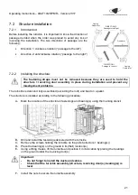
A- 

Mark the location of the structure’s fastenings and bearing(s) using the marking stencil 

B- 

Drill and install the fastenings delivered with the turnstile 

C-  Remove the screws holding the turnstile on the pallet (str bearing(s)) 
D-  Place the bearing(s) on the ground in its(their) location(s) 
E- 

Using a lifting means, lift the turnstile and position it in its location by placing the bearings 
on the ground under the revolving door(s) 

Important: 

Do not forget to install the ducts and cables


Check that the turnstile assembly (structure, revolving door(s), bearing(s)) is 
level 


F- 

Install the nuts to secure the turnstile assembly 


DIRECTION 2 

Passage to the Right 

DIRECTION 1 

Passage to the Left 

Casing 

Cable Inlet 

Casing 

Cable Inlet 

Fixed arm 

Summary of Contents for LBAT10

Page 1: ...ipment we recommend that you read these user and operating instructions carefully We are at your disposal for any additional information or comments Please contact our After Sales Service on 33 0 4 78 86 02 86 from Monday to Friday 9 am to 6 pm 451 Chemin de Champivost 69760 LIMONEST Tél 33 0 4 78 86 02 86 www grouplba com contact lbagroup fr ...

Page 2: ... MAIN CHARACTERISTICS 14 4 3 ADDITIONAL INFORMATION 15 4 3 1 Passage reducer option 15 4 3 2 Heel guard option 15 4 4 POWER SUPPLY 16 4 5 CONDITIONS OF USE 16 4 6 PERFORMANCES 16 5 OPERATING PRINCIPLE 17 6 TRANSPORT AND STORAGE 18 6 1 TRANSPORT INSTRUCTIONS 18 6 2 POST TRANSPORT INSPECTIONS 18 6 3 STORAGE INSTRUCTIONS 18 7 ASSEMBLY AND INSTALLATION 19 7 1 FOUNDATIONS AND DUCTS 19 7 1 1 LBAT 10 19 ...

Page 3: ...difying a setting 32 10 BACKING UP AND OR LOADING A PROGRAM 33 11 CLEANING AND MAINTENANCE 34 11 1 CLEANING 34 11 2 MAINTENANCE SCHEDULE 34 12 MALFUNCTIONS 35 12 1 PASSAGE IN THE EVENT OF NO VOLTAGE 35 12 2 FREQUENT FAILURES AND ADJUSTMENTS 36 13 REPAIRS 37 13 1 MODIFICATION OF THE OPERATION IN THE EVENT OF A POWER CUT 38 13 1 1 Step 1 mechanical modification of the configuration of the electromag...

Page 4: ... great deal of care in writing this information However should certain points seem incorrect or not clear please let us know we are at your disposal for anything you d like to say or any additional information you may need Before installing or repairing the turnstile read these instructions carefully The turnstile must be installed and maintained by a professional fitter in accordance with the ins...

Page 5: ...ts The key to open the turnstile hatches which gives access to the mechanism and the electrical part must be used by personnel fully aware of the risks of electrocution and crushing they are running in the event of careless handling Workers are required to check that the hatches are locked properly before leaving You alone are responsible for the instigation of and compliance with appropriate sign...

Page 6: ...ic control system The equipment must be installed inspected and switched on as per the standard in force Dispose of waste materials in compliance with the local standard in force 1 4 Intellectual property right It is forbidden to pass on the service instructions to third parties without the manufacturer s written consent The contents texts drawings figures and other illustrations are protected by ...

Page 7: ...hinery Directive 2014 35 EC Low Voltage Directive 2014 30 EC Electromagnetic Compatibility Directive 2011 65 EC ROHS Directive NF EN 61800 3 amendment A11 Table 2 Minimum immunity requirements for harmonics second environment NF EN 61800 3 amendment A11 Tables 3 and 4 Immunity requirements for voltage deviations imbalances and frequency deviations second environment NF EN 61800 3 amendment A11 Tab...

Page 8: ... turnstile can result in hazardous situations and risks of serious injuries All the following uses are deemed non compliant The control of pedestrian bicycle and or animal traffic The connection or fitting of accessories that are not approved by La Barrière Automatique in advance Any use other than those described in the compliant uses Any request for compensation of any type whatsoever following ...

Page 9: ...nce or cleaning Make sure that these personnel have read and understood this user manual Make sure that these personnel are clearly provided with personal protection equipment for any operation on the turnstile of any kind whatsoever In addition it is incumbent on the operator to Train the personnel at regular intervals in handling the turnstile and advise them of the potential risks Maintain the ...

Page 10: ...orking on electrical installations and themselves recognise the potential risks La Barrière Automatique maintenance personnel who are chosen trained and authorised by La Barrière Automatique to carry out maintenance and servicing work on the turnstiles 3 Identification Each turnstile has a rating plate fixed on the housing that indicates the type of turnstile serial number and date of manufacture ...

Page 11: ...10 20 PMR Version 2017 11 4 Technical data 4 1 Dimensions and directions 4 1 1 LBAT 10 FRONT VIEW SIDE VIEW TOP VIEW DIRECTION 2 Passage to the Right DIRECTION 1 Passage to the Left Casing Cable Inlet Casing Cable Inlet Fixed arm ...

Page 12: ...Operating Instructions LBAT10 20 PMR Version 2017 12 4 1 2 LBAT 20 FRONT VIEW SIDE VIEW TOP VIEW ...

Page 13: ...Person with Reduced Mobility FRONT VIEW SIDE VIEW TOP VIEW DIRECTION 1 Passage to the Right Door PMR Rotor Casing Cable Inlet Casing Cable Inlet DIRECTION 1 Passage to the Left DIRECTION 2 Passage to the Right DIRECTION 2 Passage to the Left Casing Cable Inlet Fixed arm ...
Page 14: ...ed with a protective cover made of 550 g m PV coated fabric Bearing system Bearing integrated into the base of the revolving door The base of the revolving door is made of stainless steel and waterproof Roof Plasticised aluminium sheet metal with rainwater drainage system LED lighting system and access hatches lockable with drive and control systems Casings Galvanised steel casings 860 mm high x 2...

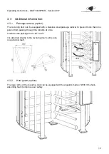
Page 15: ...l passage reducer to prevent more than one person from passing through the turnstile at once It reduces the passage from 120 to 83 It is attached directly to the revolving door s arms one on each door leaf 4 3 2 Heel guard option The lower arms of the revolving door can be equipped with heel guards made of Ø 80 mm shock absorbing foam to improve user safety 83 120 ...

Page 16: ...stance of 1 m Solid bodies Code AE4 protection against particles larger than 1 mm Wind Resistant to winds up to 140 km h Corrosive substances Code AF2 plus special conditions such as salt mist and vehicle exhaust gas Shocks Code AG3 Vibrations Code AH2 Flora and mould Code AK2 Fauna Code AL2 Electromagnetic electrostatic or ionising influences Code AM6 Solar radiation Code AN2 Lightning Code AQ2 4...

Page 17: ...the ratchet corresponding to the direction of passage is unlocked and the turnstile is therefore released in the required direction of rotation After manual rotation the ratchet will lock again to prevent a second passage If no one passes through the turnstile after the command it will automatically lock after a certain length of time adjustable and cancels the command The customer is provided wit...

Page 18: ...of straps etc 6 2 Post transport inspections When the delivery is received it must be inspected to ensure that all parts are present and that no damage has been caused during transport In the event of visible damage due to the transport or lack of parts Do not accept the delivery or with reservations only Note the extent of the damage on the delivery slip Send a claim to La Barrière Automatique 6 ...

Page 19: ...stall the turnstile according to the following recommendations The slab must be perfectly horizontal and placed at least at finished ground level The ducts must reach the turnstile s columns preferably those on which the casings are located Power supply access control and lights Direction of passage Direction of passage Exit conduit Ø40 Power supply access control and lights ...

Page 20: ...o install the turnstile according to the following recommendations The slab must be perfectly horizontal and placed at least at finished ground level We will only cover the LBAT 10 turnstile below The various procedures are the same for the LBAT 20 and LBAT PMR turnstiles Casing for access control Casing for access control ...

Page 21: ... fully assembled excluding the roof and fixed on a pallet The structure is installed according to the following procedure A Mark the location of the structure s fastenings and bearing s using the marking stencil B Drill and install the fastenings delivered with the turnstile C Remove the screws holding the turnstile on the pallet structure bearing s D Place the bearing s on the ground in its their...

Page 22: ... the roof on the turnstile s structure C Position it so that it is resting on the 4 supports D Do not attach anything yet 7 3 2 Installing the casings The turnstile s roof casings are installed according to the following procedure A Lift the roof on one side B Insert the casing by passing it through the side of the turnstile C Then pivot it so that it can be inserted inside D Place it on the rotor...

Page 23: ...ead on top B Install the M6 rounded screw heads for holding the casings on the roof 7 3 4 Installing the access hatches Once the entire roof has been installed and attached you need to install the access hatches according to the following procedure A Insert the hatch above the casing B Position the hatch attachment lugs so that they coincide with those of the casing C Then place the hatch horizont...

Page 24: ...rmal access commands The commands must be NO pulsed dry contacts o Direction 1 clockwise rotation passage to the left o Direction 2 anticlockwise rotation passage to the right Forced locking unlocking commands terminals 4 to 9 Forced commands are direct accesses to the electromagnets and are used to force the locking or unlocking of the turnstile in one direction or the other Forced commands must ...

Page 25: ...t close for 0 5 s when the turnstile rotates beyond 60 the angle after which the user can no longer pass back through The customer must use these two contacts for its access control to count the number of passages or perform an anti pass back Dusk to dawn switch terminals 41 to 46 option A dusk to dawn switch can be connected to manage the intensity of the roof s LEDs based on the luminosity Power...

Page 26: ...turnstiles are tested and adjusted in the factory However an adjustment on site may be necessary to optimise the turnstile 9 2 Commissioning the turnstile To commission the turnstile once it has been connected electrically simply close the main disconnector and the circuit breakers by raising the switches ...

Page 27: ...as in the image below By pressing on the PLC s ESC UP arrow keys the turnstile s rotary sensor self learns The following message must appear on the PLC 9 3 2 Adjusting the inductive sensor gate for persons with reduced mobility The position inductive sensor is adjusted in the following way 1 Adjust the sensor so that it is activated the sensor lamp should be lit at about 2 mm from the metal screw ...

Page 28: ...interface Menu keys Directional keys Navigation keys in the messages and menu ESC Cancellation back and enter exit from menu key OK Validation key Power supply L 24 Vdc M 0 V Connecting inputs x12 Housing for back up or recovery card Backlit display Connecting outputs x8 Menu keys Ethernet port RJ45 ...

Page 29: ...e turnstile in both directions Mill millions of passages Configuration This message indicates the off configuration of the turnstile and if this configuration has been changed If Inversion states On then the off configuration of the turnstile in the direction in question e g in this case both directions are free off Command Function Up arrow down arrow Display of different messages then counters t...

Page 30: ...e left and right directional arrows I Status of digital inputs 0 non greyed 1 greyed Q Status of digital outputs 0 non greyed 1 greyed AI Analogue input values Input 1 corresponds to the turnstile s rotary sensor LBAT10 20 only Value between 0 and 1000 0 0 V 1000 10 V There are other screens for the analogue outputs AQ There are no analogue outputs in this program I 1 9 10 20 1 2 3 4 5 6 7 8 9 0 1...

Page 31: ...configuration activated Count dir1 Passage counter in direction 1 non modifiable This value is between 0 and 999999 Once the figure of 1000000 is reached the counter of millions of passages in direction 1 is incremented No Mil dir1 Millions of passages counter in direction 1 non modifiable This value is between 0 and 999999 Count dir2 Passage counter in direction 2 non modifiable This value is bet...

Page 32: ...onal arrows and the OK key 2 Press OK again and the value starts to flash 3 Adjust the desired value using the up and down arrows 4 Press OK again to validate 5 Then press ESC to return to the list of settings 6 Press ESC again twice to exit the menu and return to the messages T Safety 1 1 T 05 00 s T 00 00 Inv Dir1 OFF Inv Dir2 OFF Count dir1 No Mil dir1 Count dir2 No Mil dir2 ...

Page 33: ... to load the program into the PLC The PLC is now programmed and you can start it using the command Start followed by YES BACK UP Backing up PLC settings to programming card Step 1 Open the card slot using a flat screwdriver Step 2 insert the card to be programmed into the slot on the PLC on the left hand side of this drawer and close it again If no program is running in the PLC move directly to st...

Page 34: ...impacts scratches etc that could encourage corrosion Inside dust removal from the mechanical and electrical sections 11 2 Maintenance schedule Frequency Operation Every six months Cleaning operations described previously Checking that all the hardware including the ground fixing and the accessories are tightened Checking the connectors on the control panel or PLC Tightening wires good contact in t...

Page 35: ...ossible configurations Direction 1 and 2 free Direction 1 free and direction 2 blocked Direction 1 blocked and direction 2 free Direction 1 and 2 blocked The prediction of a fireman unlocking associated only with the function direction blocked s in case of lack of tension is recommended There is a fireman s box by direction of passage ...

Page 36: ...ocking command is active Check the wiring of forced commands on terminals 4 to 9 of the terminal block The turnstile s rotary sensor is not working properly Repeat rotary sensor self learning see 9 3 1 Rotary sensor self learning The turnstile s operation is inversed and or inconsistent The direction 1 and direction 2 passage commands are inversed Check the wiring of passage commands on terminals ...

Page 37: ... 13 Repairs The power must be cut off before any repairs are made to the turnstile When operations take place with power on the turnstile must be disconnected from all access control systems to prevent any unexpected locking or unlocking of the turnstile ...

Page 38: ...on 1 and 2 free Direction 1 free direction 2 blocked Direction 1 blocked direction 2 free Direction 1 and 2 blocked To modify this configuration you must first switch off the turnstile s power and then open the two access hatches to the mechanism Here is the bottom view of the mechanism and the position of the electromagnets according to their configuration Direction 1 Free Direction 1 Blocked Dir...

Page 39: ...d and the ratchet A Remove the four M6 lock nuts holding the ratchet control rod B Remove the M12 lock nut holding the ratchet C Remove the rod and ratchet and pivot them 180 D Replace the rod and ratchet on the support taking care with the rod s position on the electromagnet Ratchet open rod below the electromagnet Ratchet closed rod above the electromagnet E Reinstall the M6 and M12 nuts A B C D...

Page 40: ...ns1 HT setting to On and validate see 9 4 PLC Adjustment The procedure is then finished you can check that the PLC has indeed taken the changes into account by displaying the Off Config by default message The PLC must then display On for the inversion of the direction 2 configuration Inv Dir1 OFF Inv Dir2 OFF Count dir1 No Mil dir1 Count dir2 No Mil dir2 Off Config by default Direction 1 free Inve...

Page 41: ...Operating Instructions LBAT10 20 PMR Version 2017 41 14 Wiring diagram ...

Page 42: ...Operating Instructions LBAT10 20 PMR Version 2017 42 ...

Page 43: ...Operating Instructions LBAT10 20 PMR Version 2017 43 ...

Page 44: ..._______ _________________________________________________________________________________ _________________________________________________________________________________ _________________________________________________________________________________ _________________________________________________________________________________ ________________________________________________________________...

Page 45: ...Operating Instructions LBAT10 20 PMR Version 2017 45 ...

Page 46: ...LA BARRIERE AUTOMATIQUE 451 Chemin de Champivost 69760 LIMONEST FRANCE Tél 33 0 4 78 86 02 86 E mail contact lbagroup fr Internet www grouplba com ...

Reviews: