Operating instructions
– LBA4/6/7 – 2017 Version
65
18.2.3
LBA 7/7R/74
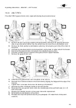
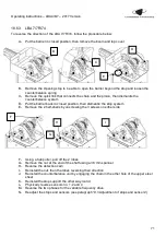
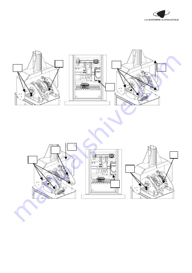
The LBA 7/7R/74 geared motor unit is replaced following the procedure below:
A-
Remove the top cover (only possible in closed position) and screw the opening stop to be
able to open the barrier further than the vertical stop (to loosen the counterbalance unit)
B-
Remove the chain-spring counterbalance system by removing the quick link of the chain on
the pinion
C- Unscrew the inductive sensors and remove them via the holes on either side of the bracket
D- Disconnect the geared motor connected to the variable frequency drive
E-
Unscrew and remove the 4 locknuts of the geared motor support brackets
F-
Remove the geared motor unit
G- Install the new geared motor unit in the place of the old one
H- Rescrew the 2 locknuts located on the boom side by aligning the flange with the edge of the
housing
I-
Tighten the 2 nut screws that secure the bearing on the bracket
J-
Rescrew the other 2 locknuts located on the sensors side
K-
Reconnect the new geared motor unit to the variable speed drive with terminals U, V, W
and to the earth
L-
Replace the inductive sensors as they were before the replacement
M- Reinstall the counterbalance on the pinion
N- Readjust the st
ops and position sensors (see paragraph “9.3 Adjustment of stops and
sensors”)
B
E
F
C
D
I
G
H
K
M
L

