Operating instructions
– LBA4/6/7 – 2017 Version
64
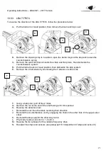
18.2.2
LBA 6/6R/63PK
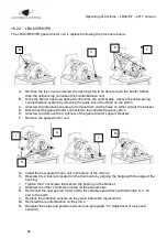
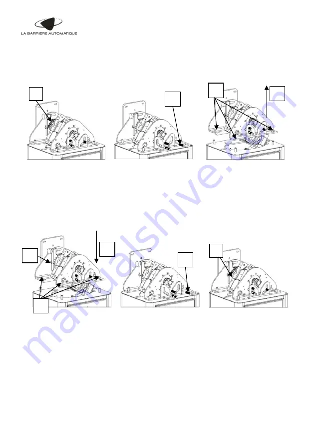
The LBA 6/6R/63PK geared motor unit is replaced following the procedure below:
A-
Remove the top cover and screw the opening stop to be able to open the barrier further
than the vertical stop (to loosen the counterbalance unit)
B-
Once the barrier has been opened further than the vertical stop, remove the chain-spring
counterbalance system by removing the quick link of the chain on the pinion
C- Unscrew the inductive sensors and remove them via the holes on either side of the bracket
D- Disconnect the geared motor connected to the variable frequency drive
E-
Unscrew and remove the 4 locknuts of the geared motor support brackets
F-
Remove the geared motor unit
G- Install the new geared motor unit in the place of the old one
H- Rescrew the 2 locknuts located on the boom side by aligning the flange with the edge of the
housing
I-
Tighten the 2 nut screws that secure the bearing on the bracket
J-
Rescrew the other 2 locknuts located on the sensors side
K-
Reconnect the new geared motor unit to the variable speed drive with terminals U, V, W
and to the earth
L-
Replace the inductive sensors as they were before the replacement
M- Reinstall the counterbalance on the pinion
N-
Readjust the stops and position sensors (see paragraph “9.3 Adjustment of stops and
sensors”)
B
C
E
F
I
G
L
M
H

