ruby standard configuration User Manual
Version: 6.4.0/2
11/179
4. The Hardware
4.3
Power Core
The 19”/1RU Power Core contains the signal processing, control system and routing matrix. It also handles all
audio, control and external Wordclock connections.
4.3.1
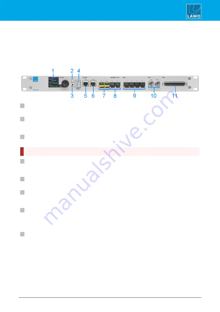
Front View
1
SYSTEM Display & Menu Control
The front panel display can be used to edit local device parameters such as the IP address.
2
STATUS LED
The STATUS LED indicates the health of the device and sync status. If the LED is blinking at regular intervals,
then the device is working properly; the LED color indicates the sync status.
3
RESET button - warm start
Press this button to perform a warm start. The button is recessed to prevent accidental operation.
A warm start will reboot the device. Do
NOT
perform a warm start while live on air!
4
DONGLE
Use this port to connect the USB memory stick containing your system's WIBU license(s). A safety cap is
available to prevent accidental removal of the dongle. If fitted, you will need a T10 star tool to remove the cap.
5
CAN
The CAN bus port connects to the control surface frame.
6
RS 422
The serial port can be used for remote control (e.g. for playout systems) and for debugging. It is usually left
unconnected.
7
CONTROL A & B (via SFP)
The two CONTROL ports connect other devices to the Power Core control system.
In a ruby standard configuration system, port A must connect to the host PC running the DisplayDock software;
port B is unused and can be left unconnected.
8
RAVENNA/AES67 A & B (via SFP)
The two RAVENNA/AES67 interfaces stream audio to and from an IP network.
In the ruby standard configuration, 32 stereo streams are transmitted and received via port A, while port B
remains unused. The streams are fully compatible with the SMPTE ST2110-30/31, AES67 and RAVENNA
standards.
Optionally, you can re-configure the system to support redundant streaming, compatible with SMPTE ST2022-
7. In this instance, you must use both interfaces: A and B.
The streaming network
must
be properly managed and configured.


