ENGLISH
Installation and User Manual
version 1.07
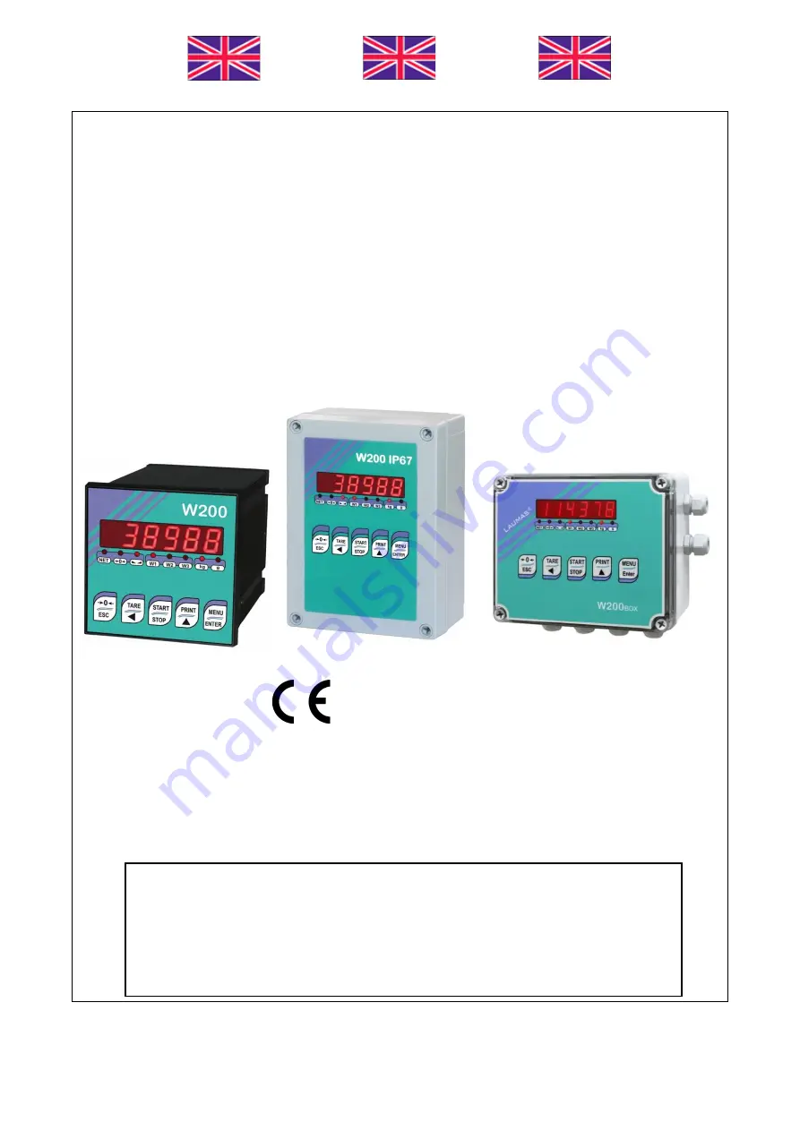
W200
Base
2014/30/EU
EN55022:2010 EN61000-6-2:2005 EN61000-6-4:2007
SYSTEM IDENTIFICATION
Page 1: ...ENGLISH ENGLISH ENGLISH ENGLISH Installation and User Manual version 1 07 W200 Base 2014 30 EU EN55022 2010 EN61000 6 2 2005 EN61000 6 4 2007 SYSTEM IDENTIFICATION...
Page 2: ...er No guarantee against misuse Batteries Laumas provides 1 year guarantee from the date of delivery note against material defects or battery manufacturing faults Disposal of Waste Equipment by Users i...
Page 3: ...LIBRATION 11 MAXIMUM CAPACITY 12 TARE WEIGHT ZERO SETTING 12 ZERO VALUE MANUAL ENTRY 12 REAL CALIBRATION WITH SAMPLE WEIGHTS 13 FILTER ON THE WEIGHT 14 ANTI PEAK 14 ZERO PARAMETERS 15 RESETTABLE WEIGH...
Page 4: ...28 WEIRIP MODE 28 TEST 28 DATE AND TIME SETTING 29 INFO MENU 29 SETPOINT PROGRAMMING 29 ALARMS 30 PRINTING EXAMPLES 32 RESERVED FOR THE INSTALLER 33 MENU LOCKING 33 MENU UNLOCKING 33 TEMPORARY MENU UN...
Page 5: ...emote control switch coils Avoid inverters in the instrument panel if inevitable use special filters for the inverters and separate them with sheet metal partitions The panel installer must provide el...
Page 6: ...l shifting and tipping relating to shocks and vibration windy conditions seismic conditions in the installation setting stability of the support structure EARTHING THE WEIGHED STRUCTURE By means of a...
Page 7: ...itation wire must be equal or similar to the one indicated in the load cell data sheet input resistance The insulation value between the shield and any other cell wire and between any other cell wire...
Page 8: ...180x130x77 mm four fixing holes 4 mm centre distance 163x113 mm Two serial ports RS485 and RS232 for connection to PC PLC up to 32 instruments max 99 with line repeaters by ASCII Laumas or ModBus R T...
Page 9: ...rsions second DISPLAY RANGE 999999 NO OF DECIMALS DISPLAY INCREMENTS 0 4 x 1 x 2 x 5 x 10 x 20 x 50 x 100 DIGITAL FILTER READINGS PER SECOND 0 012 7 s 5 300 Hz RELAY LOGIC OUTPUTS N 5 max 115 VAC 150...
Page 10: ...115 230 VAC optional version 12 INPUT COMMON VDC 0 V N NEUTRAL 115 230 VAC optional version 13 GROUND 115 230 VAC optional version 14 INPUT No 3 VDC min 5 V max 24 V otherwise ANALOG OUTPUT 0 20 o 4 2...
Page 11: ...7 14 11 9 10 13 12 16 15 16 2 16 2 to instrument OUT 1 OUT 2 OUT 3 OUT 4 OUT COMMON Current output max load 300 ohm Voltage output min load 10 kohm EXCITAT LOAD CELLS SIGNAL EXCITAT SIGNAL REF SENSE...
Page 12: ...tion during weight display press and hold down MENU and keys at the same time press MENU immediately followed by KEY Short press Long press 3 s Into menus Semi automatic zero Tare resetting Cancel or...
Page 13: ...9 MENU MAP Into menus changes are applied right after pressing the ENTER key no further confirmation is required SETPOINT SYSTEM PARAMETERS 3 s 3 s optional optional optional...
Page 14: ...tion REAL CALIBRATION WITH SAMPLE WEIGHTS If the instrument HAS NOT BEEN CALIBRATED missing plant system identification tag proceed with calibration If load cells data are unknown follow the procedure...
Page 15: ...ible to set a value between 0 50000 and 7 00000 mV V Example of 4 cell system with sensitivity 2 00100 2 00150 2 00200 2 00250 enter 2 00175 calculated as 2 00100 2 00150 2 00200 2 00250 4 The divisio...
Page 16: ...compensate zero variations due to the presence of product residues Procedure Confirm the message by pressing ENTER The weight value to be set to zero is displayed In this phase all of the LEDs are fla...
Page 17: ...the system must read zero If this does not happen it means that there is a mechanical problem affecting the system linearity WARNING identify and correct any mechanical problems before repeating the...
Page 18: ...ntil an optimum result is achieved The filter enables to stabilise a weight as long as its variations are smaller than the corresponding response time It is necessary to set this filter according to t...
Page 19: ...on the weight value is lower than the value set in this parameter and does not exceed the value the weight is reset To disable this function set 0 ZERO TRACKING from 1 to 5 default When the weight va...
Page 20: ...e inputs is set to mode see section OUTPUTS AND INPUTS CONFIGURATION when the input is closed the value will be displayed modified according to the coefficient when the input is opened the standard we...
Page 21: ...N S CHANGE FOR OTHER UNITS OF MEASURE Set in the parameter the F SCALE value divided by the conversion coefficient from kg to the new unit of measure Example The 4 load cells of 1000 kg are placed und...
Page 22: ...ve the contact will switch on the basis of gross weight the contact will switch on the basis of net weight If the net function is not active the contact will switch on the basis of gross weight relay...
Page 23: ...t see setting of the units of measure and coefficient otherwise the weight is displayed when the input is closed the data are sent for printing if in the communication protocol of either serial port t...
Page 24: ...ce again While the net weight is displayed keep pressed to display the gross weight When the key is released the net weight will be displayed again IF A SEMI AUTOMATIC TARE NET IS ENTERED IT IS NOT PO...
Page 25: ...highlighted in the picture below close the jumper shorting the pads with a drop of tin choice of a weight followed by the analog output gross or net If the net function is not active the analog output...
Page 26: ...NALOG OUTPUT TYPE Minimum Maximum 0 10 V 0 150 10 200 0 5 V 0 150 5 500 10 V 10 300 10 200 5 V 5 500 5 500 0 20 mA 0 200 22 000 4 20 mA 0 200 22 000 NOTE the analog output may also be used in the oppo...
Page 27: ...ing to its settings set continuous weight transmission protocol to RIP675 RIP6125C series remote displays the remote display shows the net weight or gross weight according to its settings set continuo...
Page 28: ...200 Hz with minimum baud rate 38400 baud 300 Hz with minimum baud rate 38400 baud delay in milliseconds which elapses before the instrument replies from 0 to 200 ms default 0 no parity default even p...
Page 29: ...is necessary to connect the above mentioned resistors DIRECT CONNECTION BETWEEN RS485 AND RS232 WITHOUT CONVERTER Since a two wire RS485 output may be used directly on the RS 232 input of a PC or remo...
Page 30: ...on WEIMOD MODE see section WEIRIP MODE WARNING in order to use the weight reading via serial port the weight reading mode must be set as see section DATA DELETION AND PROGRAM SELECTION RS485 CONNECTIO...
Page 31: ...in case of conflict the last serial set remains active Settable parameters transmission speed 2400 4800 9600 19200 38400 115200 default 9600 transmitting instrument address only for from 1 to 99 defa...
Page 32: ...al port the gross weight on the scale and works as if the load cell is directly connected to the instrument However it s not possible to perform calibrations and zero settings on the receiving instrum...
Page 33: ...display press MENU to access the setpoint setting MENU ENTER to enter a menu confirm the data entry to modify the displayed figure or menu item to select a new figure or modify the displayed menu ite...
Page 34: ...eded value higher than 999999 or lower than 999999 maximum displayable value exceeded on transmitting instrument value higher than 999999 or lower than 999999 weight too high zero setting not possible...
Page 35: ...II __O F_ __O L_ __O F_ __O L_ __O F_ aa CR RIP __O F_ __O L_ __O F_ __O L_ __O F_ __O F_ HDRIP N _ERCEL _ER_OL _ER_AD _ER_OF O__SET CONTIN _ERCEL _ER_OL _ER_AD _ER_OF O__SET For RIP remote displays i...
Page 36: ...r less than 3 seconds BASIC PRINTOUT W200 BASE Addr 01 DATE 12 09 11 14 48 12 GROSS 878 kg NET 589 kg TARE 289 kg BASIC PRINTOUT PEAK ENABLED W200 BASE Addr 01 DATE 12 09 11 14 48 12 GROSS 1204 kg NET...
Page 37: ...to indicate that this menu item is unlocked TEMPORARY MENU UNLOCKING press and simultaneously for 3 seconds it is now possible to enter and modify all menus including those which are locked By return...
Page 38: ...or approval indicating mandatory hardware code and serial number see section INSTRUMENT COMMISSIONING Configure the connection to the CLM serie intelligent junction box or to the multi channel weight...
Page 39: ...en bereinstimmt F D claration de conformit Nous d clarons avec cela responsabilit que le produit auquel se rapporte la pr sente d claration est conforme aux normes cit es ci apr s CZ Prohl en o shode...
Page 40: ......