


32
ECP5 and ECP5-5G sysCLOCK
PLL/DLL Design and Usage Guide
Low Power Features
The ECP5 and ECP5-5G PLL contains several features that allow the user to reduce the power usage of a design
including Standby mode support and Dynamic clock enable.
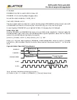
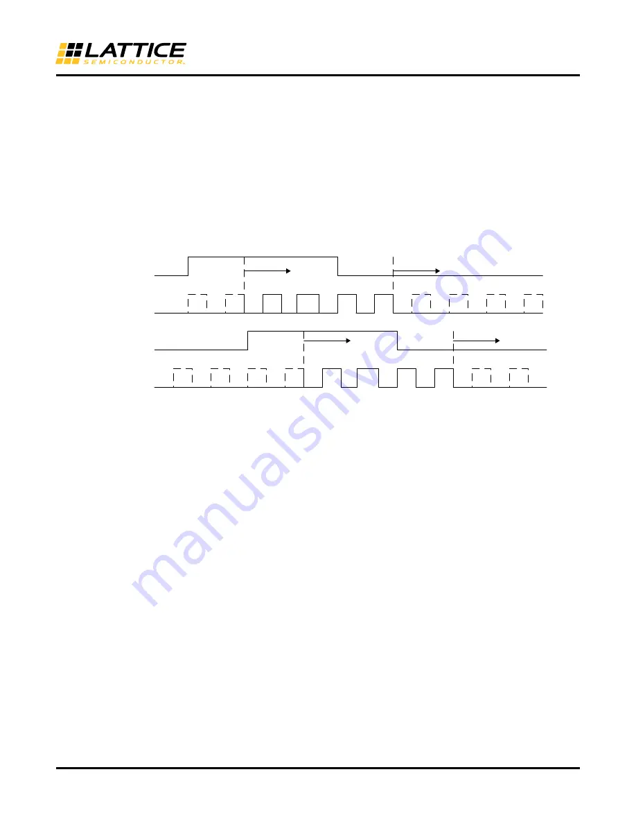
Dynamic Clock Enable
The Dynamic Clock Enable feature allows the user to glitchlessly enable and disable selected output clocks during
periods when not used in the design. A disabled output clock will be logic ‘0’. Re-enabled clocks start on the falling
edge of CLKOP. To support this feature each output clock has an independent Output Enable signal that can be
selected. The Output Enable signals are ENCLKOP, ENCLKOS, ENCLKOS2, and ENCLKOS3. Each clock enable
port has an option in the Clarity Designer GUI to bring the signal to the top level ports of the PLL. If external feed-
back is used on a port or if the clock’s output is not enabled its dynamic clock enable port is unavailable.
Figure 29. Dynamic Clock Enable for PLL Outputs
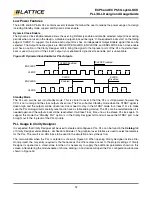
Standby Mode
The PLL can also be put into standby mode. This is similar to reset in that the PLL is still powered, however the
V
CO is not running and the clock outputs driven low. The PLL will enter Standby mode when the STDBY signal is
driven high and the outputs will be driven low. Users need to stay in the STDBY mode for at least 1 ms to make
sure the PLL analog circuits are fully reset and to have a stable analog startup. The PLL can be restarted when it is
needed again and the output clocks will be reactivated. It will take Tlock_time = 16 us to achieve PLL lock again. To
support this mode the “Standby Port” option is in the Clarity Designer GUI and will cause the STDBY port to be
brought out to the top level of the PLL module.
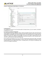
PLL Usage in Clarity Designer
It is expected that Clarity Designer will be used to create and configure a PLL. PLL can be found in the
Catalog
tab
of Clarity Designer under Module - Architecture Modules. The graphical user interface is used to select parameters
for the PLL. The result is an HDL block to be used in the simulation and synthesis flow.
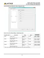
The main window when the PLL is selected is shown in Figure 30. When opening Clarity Designer inside a Dia-
mond project, the only entry required is the file name as the other entries are set to the project settings. If Clarity
Designer is opened as a stand-alone tool then it is necessary to supply the additional parameters shown on this
screen. After entering the module name of choice, clicking on Customize will open the PLL configuration window as
shown in Figure 30.
E
N
CLKOS
CLKOS
CLKOS
Ena
b
led
CLKOS
Disa
b
led
CLKOP
E
N
CLKOP
CLKOP Ena
b
led
CLKOP Disa
b
led


