BL57-RE
(E)
3-11
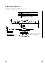
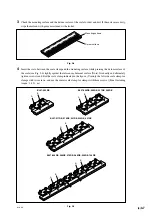
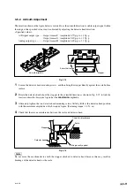
Check for interference
Bring directly against
Scale
Detector head
Stopper
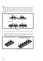
3-5-2. Azimuth Adjustment
The direction shown in the figure below is referred to as the azimuth direction. A stable output signal within
the range of the specified values can be obtained by adjusting the detector head direction.
<Specified values>
A/B signal output type ...... Output format F : Amplitude 0.7 Vp-p to 1.3 Vp-p
Output format G : Amplitude 0.8 Vp-p to 1.2 Vp-p
Analog output type ........... Output format H : Amplitude 0.6 Vp-p to 1.1 Vp-p
Fig. 3-15
1
Loosen the detector head mounting screws, and then bring the stopper directly against the scale bottom
surface.
2
Rotate the detector head about the stopper in the azimuth direction as shown in Fig. 3-15 to find the
location where the Lissajous’ figure has the
maximum
amplitude.
3
Alternately tighten the two detector head mounting screws little by little at the detector head position
with the maximum amplitude of the Lissajous’ figure. (Fastening torque: 1.4 N
·
m)
4
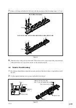
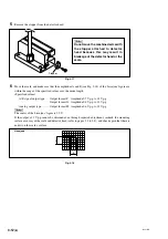
Check that there is no interference between the scale and detector head.
Fig. 3-16
Do not move the machine device with the stopper attached to detector head because this may result in
breakage of the detector head or the scale.
Azimuth direction
Azimuth direction
Stopper
Summary of Contents for BL57-RE
Page 2: ...BL57 RE...
Page 8: ...6 E BL57 RE...
Page 14: ...2 2 E BL57 RE...
Page 28: ...BL57 RE 3 14 E...
Page 40: ...5 4 E BL57 RE...
Page 52: ...8 4 E BL57 RE...
Page 54: ...9 2 E BL57 RE...
Page 66: ...2 2 G BL57 RE...
Page 80: ...BL57 RE 3 14 G...
Page 92: ...5 4 G BL57 RE...
Page 104: ...8 4 G BL57 RE...
Page 106: ...9 2 G BL57 RE...


