01572-53-000
Page 1 of 17 Issue 1 22
nd
May 2014
LASERMET
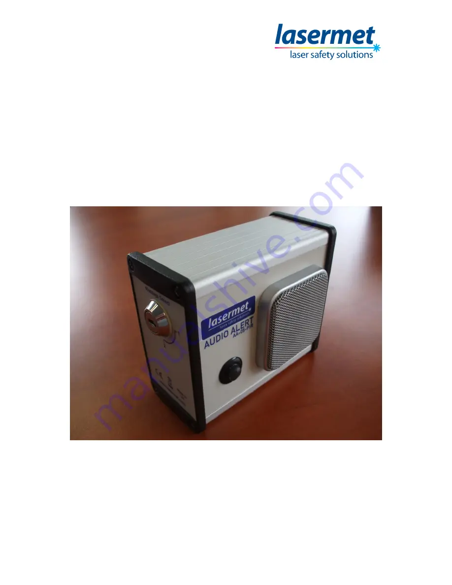
AA-05-PIR
Audio Alert
PIR Triggered
Recorded Message Playback Device
Page 1: ...01572 53 000 Page 1 of 17 Issue 1 22nd May 2014 LASERMET AA 05 PIR Audio Alert PIR Triggered Recorded Message Playback Device ...
Page 2: ...l 01572 53 000 Page 2 of 17 Issue 1 22nd May 2014 AA 05 PIR Audio Alert Instruction Manual Contents Introduction 4 Recording a Message 5 Wiring 9 Adjusting Volume 10 Installation 11 Using the AA 05 PIR 16 Specifications 17 Contact Details 17 ...
Page 3: ...00 Standard Applicable Directives Low Voltage Directive 73 23 EEC CE Directive 93 68 EEC EMC Directive 2004 108 EC European Standards to which conformity is declared EN 60598 1 2008 EN 62471 2008 EN 55015 2006 EN 61547 1995 inc A1 2000 EN 61547 2009 I hereby declare that the above listed products conform to the relevant sections of 73 23 EEC 93 68 EEC and 2004 108 EC Signed Name A Tyerman Position...
Page 4: ... has detection range of 5m from the device and a detection angle of approximately 45 degrees around the central point of the detector The messages are generally recorded at factory and can be any audio whether it be speech music or other The repetition rate and the number of repetitions of the message are factory settable to end user requirements The AA 05 PIR incorporates adjustable volume contro...
Page 5: ...alist who can record written messages onto the AA 05 PIR prior to delivery If the customer wishes to record their own messages then optional Lasermet part AA MIC can be purchased AA MIC is special microphone with custom connections specifically for the Audio Alert range The following steps indicate how recording with the AA MIC is performed Step 1 Remove Side of Case Figure 1 Removing Highlighted ...
Page 6: ...tion Manual 01572 53 000 Page 6 of 17 Issue 1 22nd May 2014 Step 2 Connect Power Figure 2 Connecting Power Cable Connect the power cable to the power input connector on the outside of the device Refer to Wiring section if in doubt ...
Page 7: ...014 Step 3 Connect AA MIC Microphone Figure 3 Connecting the AA MIC Connect the AA MIC to connector J3 Record 1 on the circuit board making sure that Pin 1 on the AA MIC is aligned with pin one on J3 Ensure power supplied on to the AA 05 PIR and the power keyswitch is in the On position ...
Page 8: ...tion Switch off power to the AA 05 PIR and ensure the message select keyswitch is in the 1 position When power is reapplied to the AA 05 PIR and motion is detected your recorded message should be heard Repeat this process until you are satisfied with the message To record the second message on the AA 05 PIR attach the AA MIC to J12 Record 2 connector on the circuit board set the message select key...
Page 9: ...d should be connected to the positive of the power supply and the blue to the negative 6 to 24VDC should be applied in order to power the unit and when motion is detected the speech routine will start If the audio signal is required to be outputted to an external amplifier or other audio device the power input connector has an extra contact to facilitate this If you are interested in this feature ...
Page 10: ...rewdriver should be used to turn the volume adjuster pictured above clockwise to increase volume or counter clockwise to decrease the volume The side of the case will need to be removed in order to carry this out instructions to do this can be found in the Recording a message section The volume adjuster is placed within the unit to prevent unauthorised changes to the volume of the device ...
Page 11: ...d easy removal of the device whilst still preventing unauthorised removal Positioning The AA 05 PIR should be mounted in a convenient position for use and wiring During installation cable connections will need to be made and allowance should be made for the installation of electrical conduit or trunking if required to gain access to the unit s location It is recommended that there must be a flat u...
Page 12: ... bracket which has no Velcro dots Using suitable screws for the wall or vertical surface you are mounting the bracket to screw through whichever of the 8 small holes on the rear of the bracket are most convenient to the installation Lasermet recommends using the holes as shown in Figure 7 The rear half of the bracket should be level and in a suitable position for utilising the AA 05 PIR ...
Page 13: ...k Velcro dots Using the supplied security bit and screwdriver in the AA 05 PIR wall mounting kit mount the front half of the bracket to the rear half of the bracket using the security screws The small holes on the sides of the bracket can be used to locate the front half of the bracket at an angle This allows the AA 05 PIR to be pointed at the location to be monitored by the PIR sensor ...
Page 14: ...s the lugs on the rear of the AA 05 PIR through the two holes on the front of the bracket You will notice that the Velcro dots on the AA 05 PIR meet with the Velcro dots on the bracket Using the supplied padlock in the AA 05 PIR wall mounting kit pass the shackle through the two holes in the lugs and secure the padlock underneath the AA 05 PIR ...
Page 15: ...AA 05 PIR Audio Alert Instruction Manual 01572 53 000 Page 15 of 17 Issue 1 22nd May 2014 Figure 10 Mounted AA 05 PIR The AA 05 PIR is now held securely in place ...
Page 16: ...t is turned to the On position the AA 05 PIR will monitor its integral PIR sensor for a signal of a person walking past the device Once the person is detected the pre installed message will play The device will then instate a delay set to user requirements at factory before being able to be triggered again by another person walking past the device The message select keyswitch will select between t...
Page 17: ... to 24VDC Power Consumption 0 48W standby 3 8W activated All figures quoted are approximate Lasermet reserve the right to alter specifications without prior notice Contact Details For sales and technical support Lasermet Ltd Lasermet House 137 Hankinson Road Bournemouth BH9 1HR United Kingdom Tel 44 0 1202 770740 Fax 44 0 1202 770730 E mail sales lasermet com Website www lasermet com ...