


Configuration Using DeviceInstaller
WiPort™ User Guide
15
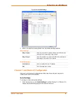
Config Pin Direction
Select whether the pin receives input or transmits output. This
field is modifiable only when
Config Pin Function
is set to
GPIO
.
Config Pin Active Level
Select the signal active level (
Low
or
High
). The default is
Low
.
5. Click
OK
to store the configurable pin settings and close the ConfigurablePin
Collection Editor.
6. Click
Apply
from the Configure Device window to apply the changes
immediately. The WiPort device automatically reboots.
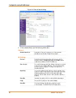
Channel 1 and Channel 2 Configuration
Channel 1 and Channel 2 configurations define how the serial port responds to
network and serial communications
.
To configure the channel configurations
:
1. From the Configure Device window for the WiPort unit, click the
Ports
tab. The
list of available ports display.
2. Click on a port number and click
Edit Settings
. The Port Properties window
opens.
3. Click
the
Port
Settings
tab. In the available fields, change the following pull
down menu options as necessary:
Baud Rate
The unit and attached serial device, such as a modem, must
agree on a speed or baud rate to use for the serial connection.
Valid baud rates are 300, 600, 1200, 2400, 4800, 9600
(default), 19200, 38400, 57600, 115200, 230400, 460800, or
921600.
Data bits
Indicates the number of bits in a transmitted data package.
Parity
Refers to the checking whether data has been lost or written
over when transmitted between computers. The default is
None
.
Stop bits
The stop bit follows the data and parity bits in serial
communication. It indicates the end of transmission.
Flow control
Flow control manages data flow between devices in a network
to ensure it is processed efficiently. Too much data arriving
before a device is prepared to manage it causes lost or
retransmitted data.
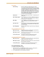
The following table demonstrates some common Interface Mode (I/F) settings:
Table 3-1. Common Interface Mode Settings
Common I/F Mode Setting
RS-232C, 8-bit, No Parity, 1 stop bit
RS-232C, 7-bit, Even Parity, 1 stop bit
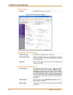
To configure advanced channel configurations:
4. From the Configure Device window for the WiPort unit, click the
Ports
tab. The
list of available ports display.