Hardware Interfaces
BOLERO40 Series Hardware Manual
31
3.
Connect your BOLERO40 to a free PC COM port using your own cable and power up
your device. Refer to the table in chapter
to indicate the serial port lines.
4.
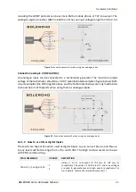
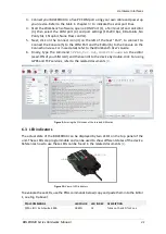
Start the Workbench software, open a COM Port (1), a Terminal (2) and an Editor
(3), then select the COM port (4) and port settings (115200 bps, 8 Data bits, No
Parity bit, 1 Stop bit, None Flow control).
5.
Next, click on the Connect icon (II) on the left of the text "Port", to connect to.
Connect the Console (5) to the COM Port and the Editor (6) to the Console on the
Connection view. For more details refer to the Workbench User's Guide.
6.
Finally, type the command
$PFAL,Cnf.Set,GSM.PIN=xxxx
on the editor
(xxxx=PIN of your SIM card) and then send it to the device by double-click. For using
GPRS and TCP services, refer to the related documents
Figure 9:
Entering the PIN codes of the inserted SIM cards.
6.3
LED indicators
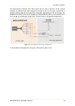
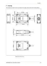
The actual state of the BOLERO40 can be displayed by two LED’s on the top panel of the
unit. These LEDs are programmable and can be used to show different states of the device.
References how to use these LEDs can be found in the related documents
Figure 10:
View of LED indicators
To evaluate these LEDs, use the PFAL commands below (copy and paste them into the Editor
1, see Fig. 9 above):
PFAL COMMANDS
LED COLOR LED INDEX DESCRIPTION
$PFAL,IO
12
.Set=hpulse,2000
GREEN
12
Turns on the LED for 2 sec.


