background image


Hardware Interfaces 


BOLERO40 Series Hardware Manual 


29 


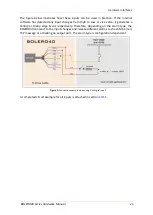
Figure 6.1:

 Use IGN line to wake BOLERO40 up from IGN-Sleep 

6.1.2


Serial Port 0 - Serial communication signals (RTD and TXD) 

This serial port can be connected to an external serial communication device such as an 

RFID device. However it offers free of charge serial communication with a PC for evaluation 

and configuration purposes. To connect an RFID serial device to this serial port and use it, 

you need to purchase the corresponding activation key. Please contact Lantronix sales team 

for more details. 
BOLERO40  incorporates a full duplex serial channel which allows two devices to 

communicate directly with each other via the RS232 serial port. All supported variable baud 

rates are software-controlled. The signals on these pins are obtained to RS232 compatible 

signal levels.


6.1.3


Description of 1-Wire interface  

A 1-Wire bus uses only one wire for signaling and power. Up to four 1-Wire devices can be 

connected to the 1-wire interface of the BOLERO40  at the same time. The information 

received from 1-Wire sensors can then be sent to the remote TCP server using PFAL 

commands/scripts.  


Summary of Contents for BOLERO40 Series

Page 1: ...Version 1 0 3 Modified Thursday January 23 2020 BOLERO40 Series Hardware Manual Part Number PMD 00012 Revision B January 2020...

Page 2: ...ive Suite 100 Irvine CA 92618 USA Toll Free 800 526 8766 Phone 949 453 3990 Fax 949 453 3995 Technical Support Online https www lantronix com support Sales Offices For a current list of our domestic a...

Page 3: ...or software is subject to the terms of the applicable license OPEN SOURCE SOFTWARE IS DISTRIBUTED WITHOUT ANY WARRANTY INCLUDING ANY IMPLIED WARRANTY OF MERCHANTABILITY OR FITNESS FOR A PARTICULAR PU...

Page 4: ...1 Safety for Li Ion batteries 12 2 11 1 Safety precautions while charging the battery 12 2 11 2 Safety precautions while discharging Li Ion battery 13 2 11 3 Safety precautions when replacing the batt...

Page 5: ...ow to use IGN Ignition 28 6 1 2 Serial Port 0 Serial communication signals RTD and TXD 29 6 1 3 Description of 1 Wire interface 29 6 2 Inserting a SIM card into the SIM holder 30 6 2 1 Entering PIN of...

Page 6: ...n 8 wire harness with an 8pin connector at the cable s end The table below shows the available models of BOLERO40 Series MODEL NAME TERRITORIES OR OPERATOR S CELLULAR TYPE 1 BAND S 2 FALLBACK MODE 1 B...

Page 7: ...s installed one of BOLERO40 series device which consists of A GNSS receiver to receive signals from GPS GLONAS Galileo BeiDou navigation satellites A GSM 2G 3G modem to transmit the data by radio to t...

Page 8: ...0 Series is shipped in a cardboard box with following content Packing in cardboard box Overall size 170mm x 120mm x 56mm Weight 210 gr cardboard box Packaging insert and quick setup guide Figure 2 BOL...

Page 9: ...s_ECO DRIVE GPS pdf This document contains information of how to use the features of the GPS ECO DRIVE supported as PREMIUM FEATURE in the firmware version avl_2 11 0 and above 6 AppNotes_AES_TCP pdf...

Page 10: ...tional costs can result from the use of the SIM cards which are to be borne by the purchaser client of the devices The seller does not cover the extra costs for the use of the devices The seller gives...

Page 11: ...them on the ground only with crew permission Do not use them in the air To prevent possible interference with aircraft systems Federal Aviation Administration FAA regulations require you to have permi...

Page 12: ...tend the life expectancy of battery please follow the safety rules listed below before using BOLERO40 device with battery option Do not place the battery on in or near fires apparatus that provide hea...

Page 13: ...you must consider when replacing the battery The lithium battery must be handled correctly to avoid possible danger Replace the battery only with the same battery that comes with the device Use of ano...

Page 14: ...ety standards BOLERO40 meet the safety standards for RF receivers and the standards and recommendations for the protection of public exposure to RF electromagnetic energy established by government bod...

Page 15: ...s 8 data bits no parity 1 stop bit no flow control Premium feature for connection to third party products 1 Wire line for connecting 1 Wire slave devices such as iButton temperature sensors etc 2 x In...

Page 16: ...ower mode doze GPS fix valid GPRS and TCP connected Transmit Data 159 190 mA Sending data over TCP Table 3 Current consumption at 12 VDC All measurements performed under Tamb 23 C V IN 24 VDC BOLERO45...

Page 17: ...cted Transmit Data 205 258 mA Sending data over TCP Table 3 2 Current consumption at 3 8 VDC Sleep Modes Avr power consum in sleep Unit 12 24 3 8V IGN 3 2 4 mA IGN Ring 9 6 18 mA IGN Timer 3 2 4 mA IG...

Page 18: ...ass 4 2 W at EGSM900 850 MHz Class 1 1 W at GSM1800 and GSM 1900 MHz MOBILE CONNECTIVITIES GPRS multi slot class 12 GPRS mobile station class B DATA HSPA Downlink transfer max 7 2 Mbps Uplink transfer...

Page 19: ...n of up to three GNSS systems GPS Galileo together with BeiDou or GLONASS GPS L1 C A POSITION ACCURACY Position 2 5 m ACQUISITION Cold starts 28 sec Tracking 164 dBm SENSITIVITY Cold start 148 dBm OPE...

Page 20: ...but NOT protected against continuous overvoltage 5 1 1 Power lines on the 8 wire harness One DC IN pin on the main 8 pin port is dedicated to connect a constant 12 24 volt DC voltage source and the BR...

Page 21: ...1 20 00 Device wakes up when timeout has expired Motion 200 Device wakes up when the set motion value is exceeded ExtPwrDetect Device wakes up when external power connection is detected ExtPwrDrop Dev...

Page 22: ...determine if the external hardware serial ports are configured as DTE Data Terminal Equipment or DCE Data Communications Equipment BOLERO40 is designed for use as DCE devices Based on the conventions...

Page 23: ...utton and 1Wire temp sensors VOUT 3 3 VDC 5 YELLOW IO2 IN OUT Software controlled pins Each pin has dual functions as analogue or digital As digital they can be used either as input or output Outputs...

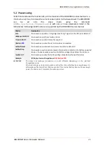
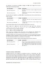
Page 24: ...ated with corresponding PFAL commands For more details refer to the related documents 1 Analogue voltages of up to 32 0V with a 12 bits resolution can be processed and remotely evaluated by a server a...

Page 25: ...the NTC diagram above and the Tachometer below are only illustrations to show the aim of these IOs when using them as analogue inputs Figure 3 1 Connection example 2 when using it as analogue input 6...

Page 26: ...versa it generates a Falling or Rising edge Event respectively Therefore depending on the alarm type the BOLERO40 can react to the input changes and release different alarms such as SMS email TCP mess...

Page 27: ...one or more alarms that activate these outputs when specific events occur e g PFAL Cnf Set AL0 IO e8 redge IO5 Set cyclic 1000 2000 In order to evaluate this alarm send firstly this alarm configurati...

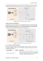
Page 28: ...It wakes up the system BOLERO40 from the IGN sleep mode when sleeping it can monitor the vehicle ignition state and report store the trip START and STOP by using the events IO e8 redge and IO e8 fedge...

Page 29: ...he corresponding activation key Please contact Lantronix sales team for more details BOLERO40 incorporates a full duplex serial channel which allows two devices to communicate directly with each other...

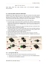
Page 30: ...together then unscrew the 4 x TORX 8 screws Crews may also be delivered in a separate plastic bag 2 Carefully remove the half part of the casing If the battery harness is connected to the 3pin white c...

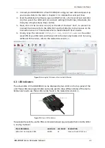
Page 31: ...the Workbench User s Guide 6 Finally type the command PFAL Cnf Set GSM PIN xxxx on the editor xxxx PIN of your SIM card and then send it to the device by double click For using GPRS and TCP services r...

Page 32: ...he device with permanently powered by car battery instead of its backup battery The device should be configured to automatically switch from main power to battery backup when main power is not availab...

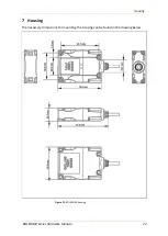
Page 33: ...Housing BOLERO40 Series Hardware Manual 33 7 Housing The necessary dimensions for mounting the housing can be found in the drawing below Figure 12 BOLERO40 housing...

Page 34: ...company could void the user s authority to operate the equipment Statement according to FCC part 15 105 NOTE This equipment has been tested and found to comply with the limits for a Class B digital de...

Page 35: ...connected via the ignition port the device switches off when the car ignition is turned off Please use a slow 2A fuse No further current consumer should be connected on the same port use the same fus...

Page 36: ...and gives also a brief description for each of them For further description about these protocols refer to the related documents 1 These protocols can be sent via SMS TCP data call serial port e mail...

Page 37: ...e state values of the motion sensor BIN The user protocol contains GPS time date position course and speed data in binary format small sized only 21 characters Table 9 1 Lantronix Output Messages 9 4...

Reviews: