


Hardware Interfaces
BOLERO40 Series Hardware Manual
25
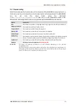
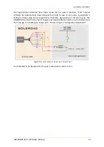
including the GPIOP protocol can be sent via SMS a mobile phone or TCP to a server. The
analog-to-digital converter (ADC) inside the unit has an input voltage range from 0 to 2.5 V.
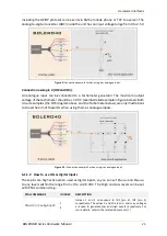
Figure 3:
Connection example 1 when using it as analogue input.
Connection example 2 (IO2 and IO3)
:
An analogue input can be connected to a tachometer generator. The maximum output
voltage of the tachometer should be + 32.0 V (see illustrated example in figure below). Both
circuit examples (the NTC diagram above and the Tachometer below) are only illustrations
to show the aim of these IOs when using them as analogue inputs.
Figure 3.1:
Connection example 2 when using it as analogue input.
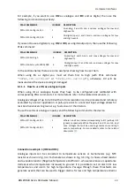
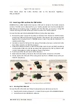
6.1.1.2
How to use IOs as digital Inputs
These pins are high active when used as digital inputs, so you can set
V
IN(LOW)
and
V
I
N(HIGH)
to any levels within the range from +0 to +32.0 VDC. The High and Low levels can be set
with PFAL command (e.g.
PFAL COMMANDS
IO INDEX
DESCRIPTION
PFAL,IO
1[2]
.Config=DI,5,10
1
2
Indices 1 and 2 correspond to IO1 (pin 4), IO2 (pin 5)
respectively. The values 5 and 10 are min. and max. voltages
are used to generate Low and High events respectively.
For
more details, refer to the related documents