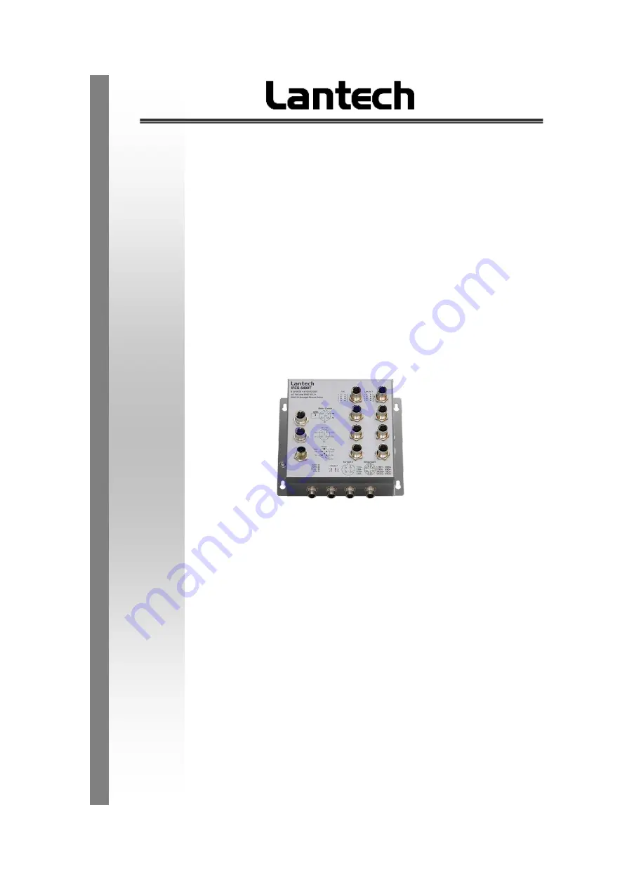
I(P)ES-5408T-X-IGN Series
8 10/100TX + 4 10/100/1000T L2+ (w/8 PoE at/af)
Industrial Managed Ethernet Switch
I(P)ES-5408T-D-IGN Series
12 10/100TX L2+ (w/8 PoE at/af)
User Manual (Hardware)
Sep. 2021
Page 1: ...X IGN Series 8 10 100TX 4 10 100 1000T L2 w 8 PoE at af Industrial Managed Ethernet Switch I P ES 5408T D IGN Series 12 10 100TX L2 w 8 PoE at af Industrial Managed Ethernet Switch User Manual Hardwa...
Page 2: ...y an STP network cable in demanding electrical environments Examples of demanding indoor environments are where the network cable is located in parallel with electrical mains supply cables or where la...
Page 3: ...consent of Lantech Communications Global Inc Products offered may contain software which is proprietary to Lantech Communications Global Inc The offer or supply of these products and services does no...
Page 4: ...occur in a particular installation If this equipment does cause harmful interference to radio or television reception which can be determined by turning the equipment off and on the user is encourage...
Page 5: ...ption 6 2 1 Physical Dimension 6 2 2 Front Panel 8 2 3 Package Content 9 2 4 IP Protection 9 2 5 LED Indicators 12 Chapter 3 Hardware Installation 14 Chapter 4 Console Management 19 4 1 Connecting to...
Page 6: ...0 100TX d coded 4 10 100 1000T x coded by M12 provides L2 wire speed and advanced security function for network aggregation deployment Lantech IPES 5408T D IGN IP54 is a high performance L2 Gigabit up...
Page 7: ...describe the Industrial switch s hardware spec port cabling information and wiring installation 2 1 Physical Dimension I P ES 5408T X IGN 67 Aluminum case IP 67 215 W x 200 H x 76 7 D mm I P ES 5408T...
Page 8: ...7 I P ES 5408T X IGN 67 Aluminum case IP 67 215 W x 200 H x 76 7 D mm I P ES 5408T X IGN 54 Aluminum case IP 54 182 W x 179 5 H x 76 5 D mm...
Page 9: ...8 2 2 Front Panel Front panel of IPES 5408T X IGN Front panel of IPES 5408T D IGN...
Page 10: ...ed by the International Electrotechnical Commission IEC Solid particle protection The first digit indicates the level of protection that the enclosure provides against access to hazardous parts e g el...
Page 11: ...vertically falling drops shall have no harmful effect Test duration 10 minutes Water equivalent to 1 mm rainfall per minute 2 Dripping water when tilted up to 15 Vertically dripping water shall have...
Page 12: ...of 3 m 7 Immersion up to 1 m Ingress of water in harmful quantity shall not be possible when the enclosure is immersed in water under defined conditions of pressure and time up to 1 m of submersion Te...
Page 13: ...provides the description of the LED status and their meanings for the switch LED Color Status Meaning R M Green On The switch unit is owner switch of ITU Ring Off The switch is not owner switch PWR1 G...
Page 14: ...13 ES Off The port is not operating in PoE mode IPES P9 P12 Link Act On A network device is detected Blinking The port is transmitting or receiving packets from the TX device Off No device attached...
Page 15: ...of the switch Note Please check the power connector has been connected to the switch correctly before you turn on the power resource Voltage of Power Input Non PoE model 24V model The power input volt...
Page 16: ...vehicle has been turned off by driver the switch still can still offer power to the equipment via PoE connection from the battery for a maximum of 11 minutes Dual Power Input The power input can be su...
Page 17: ...5VDC signal 3 1 4 Fitting the device grounding Install the system in a dry and clean area to protect the switch to get exposed with dirt Plug the connector to the power supply plug then turn on the p...
Page 18: ...17 Ground screw of I P ES 5408T IGN switch 3 1 5 Connect the M12 connector with RJ 45 data cable ports are not used shall be caped that comes with the package to insulate the surrounding...
Page 19: ...LED make sure the switch was in working status Note The protection class IP67 IP54 is only achieved when bolted together The other components attaching to the system have to meet with the IP67 IP54 pr...
Page 20: ...r to the console port of the switch The connected terminal or PC must support the terminal emulation program 4 2 Login in the Console Interface When the connection between Switch and PC is ready turn...
Page 21: ...pt appears Key in admin default value for both User name and Password use Enter key to switch then press Enter and the Main Menu of console management appears Please see below figure for login screen...