Lanner FW-7580 User Manual Download Page 8

5

Introduction

Chapter 2

Network Application Platforms

Chapter 2:  

Hardware Setup

Preparing the Hardware Installation

To access some components and perform certain service 

procedures, you must perform  the following procedures 

first. 

WARNING:

 To reduce the risk of personal injury, 

electric  shock,  or  damage  to  the  equipment, 

remove the power cord to remove power from the 

server. The front panel Power On/Standby button 

does  not  completely  shut  off  system  power. 

Portions  of  the  power  supply  and  some  internal 

circuitry remain active until AC power is removed.

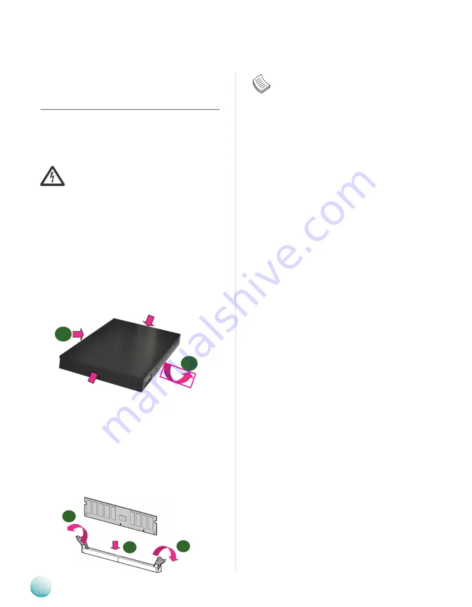
Unpower the FW-7580 and remove the power cord.

1. 

Unscrew the 3 threaded screws from the top cover of 

2. 

the FW-7580 System.

Slide  the  cover  backwards  and  open  the  cover  

3. 

upwards.

Installing the System Memory 

The  motherboard  supports  DDR2  memory  that  features 

data transfer rates of 667 and 800 MHz to meet the higher 

bandwidth  requirements  of  the  latest  operating  system 

and  Internet  applications.    It  comes  with  two  Double 

Data  Rate(DDR2)    Dual  Inline  Memory  Modules  (DIMM) 

sockets.

Open the DIMM slot latches.

1. 

Install the DIMM.

2. 

Note:


All DIMMs installed must be the same speed 

1. 

(DDR2 667 or 800). Do not install DIMMs 

supporting different speeds.

The  motherboards can support up to 8 GB 

2. 

memory capacity in maximum.  However, due 

to the memory address limitation on 32-bit 

Windows OS, when you install 4GB or more 

memory on the motherboard, the actual usable 

memory for the OS can be about 3GB or less.  For 

effective use of memory, we recommend that you 

do any of the following:

Use a maximum of 3GB system memory if you are 

using a 32-bit Windows OS. 

OR

Install a 64-bit Windows OS when you want to 

install 4GB or more on the motherboard.

For more details, refer  to the Microsoft© support 

site.

Installing the  Hard Disk

The  system  can  accomdate  two  Serial-ATA  disks.  Follow 

these steps to install a hard disk into the FW-7580:

Unsrew the 4 screws on the hard disk tray to take out 

1. 

the hard disk tray from the system.
Place hard disk on the hard disk tray and align the holes 

2. 

of the hard disk with the mounting holes on the tray.
Secure the hard disk with 4 mounting screws on the 

3. 

hard disk tray.
Connect the Serial-ATA power and hard disk cables to 

4. 

the hard disk’s connectors respectively.
Plug the Serial-ATA  cable to the Serial-ATA Connector 

5. 

on the main board.
Repeat steps 2 to 5 to install a second disk (if there is 

6. 

one).
Put the hard disk tray with the installed hard disk back 

7. 

to the system and secure it with the mounting screws.


1

2

1


2

1


Summary of Contents for FW-7580

Page 1: ...Network Application Platforms Hardware platforms for next generation networking infrastructure FW 7580 User s Manual Publication date 2010 04 15...

Page 2: ...inal manufacturer assumes no responsibility for its use nor for any infringements upon the rights of third parties that may result from such use Acknowledgement Intel Pentium and Celeron are registere...

Page 3: ...the Heat Sink Installation 6 Riser Card Installation 7 Chapter 3 Motherboard Information 8 Block Diagram 8 Motherboard Layout 9 Jumper Settings 10 Chapter 4 BIOS Settings 12 Updating the BIOS 12 Acces...

Page 4: ...Memory Technology Dual channel DDR2 800 667 MHz Max Capacity 8GB Socket 240P DIMM x 2 OS Support Windows Linux OpenBSD FreeBSD Storage HDD Bay s 2 5 x 1 Storage Interface Serial ATA x 2 CompactFlash...

Page 5: ...ntains the following items FW 7580 Network Security Platform Power cable 1 crossover Ethernet cable 1 8 meter 1 straight through Ethernet cable 1 8 meter 1 RJ 45 to DB 9 female console cable Serial AT...

Page 6: ...n purpose Terminal Configuration Parameters 115200 baud 8 data bits no parity 1 stop bit no flow control F5 Two USB 2 0 Ports It connects to any USB devices for example a flash drive F6 Management Por...

Page 7: ...d 3 R4 VGA Port A VGA connector for connecting the monitor R5 RS 232 Serial Port It can be connected to a terminal computer for diagnostic purpose R6 USB2 0 Port It connects to any USB devices for exa...

Page 8: ...not install DIMMs supporting different speeds The motherboards can support up to 8 GB 2 memory capacity in maximum However due to the memory address limitation on 32 bit Windows OS when you install 4...

Page 9: ...w the two screws to fasten it on the case Note The CPU heat sink could only be installed in only 1 one direction as shown in the picture To protect the CPU socket pins retain the CPU 2 cap when the CP...

Page 10: ...ovide a PCI E connector for installing an additional adaptor in a compact system lke the FW 7580 a riser card has to be installed Align the riser card with the PCI E golden finger 1 connector Insert t...

Page 11: ...rk Application Platforms Chapter 3 Motherboard Information Block Diagram The block diagram depicts the relationships among the interfaces or modules on the motherboard Please refer to the following fi...

Page 12: ...Cable Connector VGA Cable Connector Front LCD module Connector Clear CMOS System Power Button Connector ATX Power Connector Reset Switch M14 USB Cable Connector SATA 1 2 Connec tors Keyboard and Mouse...

Page 13: ...s storage For details of pin assignment please refer to the User s Manual M9 Keyboard and mouse interface Connectors J16 It is for connecting the PS 2 keyboard and mouse interface cable M10 Front LCD...

Page 14: ...nnectors J13 COM2 It is for connecting the RS 232 serial port module cable M19 CPU Socket The LGA 775 socket is for connecting the CPU M20 CPU Fan Connectors CON1 CON2 CON3 The 4 pin connector is for...

Page 15: ...ty please contact us either through the sales rep or technical support Note For the update version of the BIOS image please visit Lanner s support page at http assist lannerinc com Then select support...

Page 16: ...ssible Being a menu driven program it lets you scroll through the various sub menus and make your selections from the available options using the navigation keys Note This manual describes the standar...

Page 17: ...On the other hand Options in blue can be modified The right frame displays the key legend Above the key legend is an area reserved for a text message When an option is selected in the left frame it i...

Page 18: ...t The sub menus are described on the following pages IDE Configuration Settings You can use this screen to select options for the IDE Configuration Settings Use the up and down Arrow keys to select an...

Page 19: ...IOStoautomatically detect the IDE disk drive type attached to the specified channel This setting should be used if an IDE hard disk drive is attached to the specified channel This is the default setti...

Page 20: ...is value if the IDE disk drive support cannot be determined This is the default setting 0 Set this value to allow the BIOS to use PIO mode 0 It has a data transfer rate of 3 3 MBs 1 Set this value to...

Page 21: ...IOS to use Ultra DMA mode 3 It has a data transfer rate of 44 4 MBs To use this mode it is required that an 80 conductor ATA cable is used UDMA4 Set this value to allow the BIOS to use Ultra DMA mode...

Page 22: ...is the default setting Enabled Set this value to prevent the hard disk drive from being erased IDE DetectTime Out Seconds Set this option to stop the AMIBIOS from searching for IDE devices within the...

Page 23: ...from searching the IDE bus for IDE disk drives in 35 seconds SuperIO Configuration In this screen you will be able to modify the IRQ address of the serial and parallel ports which are provided by the...

Page 24: ...is best to set this port to Disabled 2E8 IRQ3 Set this value to allow the serial port to use 2E8 as its I O port address and IRQ 3 for the interrupt address If the system will not use a serial device...

Page 25: ...ue to prevent the parallel port from accessing any system resources When the value of this option is set to Disabled the printer port becomes unavailable 378 Set this value to allow the parallel port...

Page 26: ...ECP uses the DMA protocol to achieve data transfer rates up to 2 5 Megabits per second ECP provides symmetric bi directional communication Parallel Port IRQ This option specifies the IRQ used by the...

Page 27: ...ME 98 NT and MS DOS Normally if this option is not enabled any attached USB mouse or USB keyboard will not become available until a USB compatible operating system is fully booted with all USB driver...

Page 28: ...en press Enter to display the configuration options CPUFan Mode Setting It allows you to configure the smart fan feature You can manually turn on the CPU fan or set the target CPU temperature at which...

Page 29: ...Sec When set to 10 Sec the BIOS will wait for up to 10 seconds for the USB flash drive to initialize Emulation Type USB Emulation refers the system being able to boot to a USB drive Normally if this...

Page 30: ...the value of the selected option The settings are described on the following pages The screen is shown at right Remote Access You can disable or enable the BIOS remote access feature here Option Descr...

Page 31: ...w you to select 57600 as the baud rate transmitted bits per second of the serial port 19200 8 n 1 Set this value to allow you to select 19200 as the baud rate transmitted bits per second of the serial...

Page 32: ...a loss make sure you have a backuporrecoverymethodforanydata protected or encrypted by the TPM Lan Bypass Control In this screen you can configure the Lan Bypass functionality Lan Bypass for Port 1 an...

Page 33: ...C power interruption Power On When setting to Power on the system turns on automatically after a power interruption Last State When setting to Last State the system goes into whatever the state was be...

Page 34: ...he BIOS to skip some power on self tests POST while booting to decrease the time needed to boot the system When set to Disabled BIOS performs the complete series of tests Select Enabled or Disabled to...

Page 35: ...rt up sequence even when an error is detected Hit DEL Message Display When this item is set to Enabled the system displays the message Press DEL to run Setup during the start up sequence Interrupt 19...

Page 36: ...a Supervisor and a User password If you use both passwords the Supervisor password must be set first The system can be configured so that all users must enter a password every time the system boots o...

Page 37: ...e sub menu You can use the sub menu to change the supervisor password Change User Password Select this option and press Enter to access the sub menu You can use the sub menu to change the user passwor...

Page 38: ...n parameters can take effect Discard Changes and exit Select this option to discard changes and exit Discard Changes and Exit Setup Now Select this option to quit Setup without making any permanent ch...

Page 39: ...essor s reset signal is asserted Thus the processor will be restarted as if a human operator had cycled the power For sample watchdog code see watchdog folder on the Driver and Manual CD To program th...

Page 40: ...ettings in the BIOS Setup 2 menu for FW 7580 Please refer to the Remote Access Settings on Chapter 4 BIOS Settings BIOS Advanced Remote Access Configuration Serial Port Mode 115200 8 n 1 Configure Con...

Page 41: ...un LLCM2 for excution Function Clear_LCM This Function is Clear the LCD Module Direct write the function to your program Read_KeyPad ThisFunctiongettheKeyPadnumberifuserpressed key Direct write functi...

Page 42: ...AN Bypass function When the system powers off it can be forced to enable 1 the LAN Bypass function through the BIOS settings See BIOS Settings User can enable or disable the LAN Bypass function 2 whic...

Reviews: