


4-8
F-808-R0
OPERATING THE B40I4 FORKLIFT
WARNING
WARNING
Refilling an LPG Tank
NOTE
The following instructions are general procedures. There
are variations in equipment for filling LPG tanks. The
local authorities that have jurisdiction have specific rules
and regulations for filling LPG tanks. Make sure these
rules and regulations are available and understood.
Use the following procedure to fill the LPG tank:
1.
Check the LPG tank to make sure it needs filling.
2.
During the fill operation, the LPG tank must be in a
position so that the liquid level indicator will always
be in the vapor space above the liquid level.
3.
Open the liquid outlet valve and by-pass return valve
on the storage tank.
4.
Start the pump.
5.
Connect the supply hose to the quick disconnect
fitting on the LPG tank. If the LPG tank has an
auxiliary fill fitting, connect the supply hose to this
fitting. Make sure the correct adapter is used to
connect the supply hose to the auxiliary fill fitting.
6.
Open the vent valve on the liquid level indicator.
7.
Open the shut-off valve on the LPG tank.
8.
Open the valve on the end of the supply hose.
9.
Watch for a discharge from the vent valve on the
liquid level indicator. When a cloud of visible vapor
appears, the LPG tank is full.
10. Do not fill the LPG tank more than the maximum level
indicated by the liquid level indicator.
11. Immediately close the valve at the end of the supply
hose.
12. Close the vent valve on the LPG tank.
13. Close the shut-off valve on the LPG tank.
14. Disconnect the supply hose.
15. Stop the pump.
16. Close the liquid outlet valve and the by-pass return
valve on the storage tank.
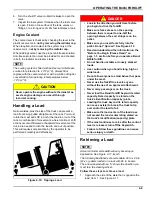
Installing an LPG Tank
Use the following procedure to install the LPG tank:
1.
Before the LPG tank is installed on the lift truck,
check the operation of the fuel gauge. Look at the
fluid gauge and move the tank. If the gauge needle
does not move, a new tank must be installed.
WARNING
2.
Install the LPG tank in its bracket so that the
alignment pin is in the correct hole.
3.
Close the latch on the tank bracket.
4.
Connect the quick disconnect fitting to the shut-off
valve on the LPG tank.
5.
Use your hand to tighten the fitting. Wrenches are not
required on an operational fitting.
Use only an approved LPG tank. Do not use an
LPG tank that is damaged. A damaged LPG tank
must be removed from service.
• Close the shut-off valve on the tank when
parking the lift truck more than momentarily.
• Do not park the lift truck near heat or ignition
sources.
• Do not store LPG tanks near heat or an open
flame. For complete instructions on the
storage of LPG fuels, refer to ANSI/NFPA 58
and 505.
• LPG is extremely flammable. When checking
or filling an LPG tank stop the engine and
stop smoking.
• Frost on the surface of the tank or at the
valves/fittings and/or the odor of LPG fuel
indicates a leak. Inspect the LPG system and
repair a leak immediately. An LPG fuel leak
can create an explosion and fire hazard. Do
not attempt to start the engine if there is a
leak in the LPG fuel system.
• Only trained and authorized personnel are
permitted to operate refueling equipment.
• LPG tanks are heavy. The weight of an LPG
tank can exceed the maximum recommended
weight for safe lifting by an individual. Get
assistance when lifting or lowering an LPG
tank. Use correct lifting procedures.
• Fill the LPG tanks outdoors. Stay at least 50
feet (15 meters) from buildings, motor
vehicles, electrical equipment, or other
ignition sources. Stay at least 15 feet (5
meters) from LPG storage tanks.
Make sure the alignment pin extends through the
correct hole in the rim of the LPG tank. The hose
or the fittings can be damaged if the LPG tank is
not installed in the correct position. A damaged
hose or fitting can release LPG fuel and cause a
fire hazard and/or explosion.
Summary of Contents for Bendi B40i4
Page 2: ......
Page 12: ...1 4 F 808 R0 FORKLIFT SAFETY AND FAMILIARITY Figure 1 2 Decals...
Page 18: ...1 10 F 808 R0 FORKLIFT SAFETY AND FAMILIARITY Table provided for general use NOTES...
Page 24: ...2 6 F 808 R0 RECEIVING AND INSPECTION Table provided for general use NOTES...
Page 54: ...4 16 F 808 R0 OPERATING THE B40I4 FORKLIFT Table provided for general use NOTES...
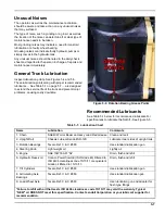
Page 62: ...5 8 F 808 R0 Figure 5 5 Lubrication Points...
Page 64: ...5 10 F 808 R0 Table provided for general use NOTES...