


g.
Insert bearing cups into the hub.
h.
Clean the mounting surfaces with a good
grade commercial cleaner and soft rag. Dry
all component parts with a clean, absorbent
cloth or paper. Lubricant will not adhere to
surfaces wet with solvent.
i.
Install inner bearing, cone, and seal.
IMPORTANT
DO NOT MIX NEW CUPS WITH OLD CONES OR
NEW CONES WITH OLD CUPS.
j.
Place the hub or wheel over the axle spindle
being careful to align the hub bore with the
axle. Do not damage the seal. Support the
hub assembly until the outer bearing cone
and spindle nut are installed, to avoid damag-
ing the seal.
k.
Install the outer bearing cone and inner
spindle nut, tightening the nut until it is snug
against the outer bearing cone. Remove the
hub support allowing the hub to rest on the
bearings.
l.
Install and adjust bearings
(See Section
4-10, Wheel Bearing Lubrication and Ad-
justment).
m.
Install the hub cap with the proper gasket.
Tighten the cap screws of the hub cap to 15
to 20 ft-lbs. of torque.
n.
Remove the filler plug and fill the hub cavity
to the recommended level with a gear type
oil.
o.
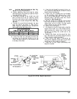
Place the drum over the hub and brake
shoes being careful not to damage the
threads on the studs. Make sure the drum
seats flat against the hub flange and mates
properly with the hub pilot. There should be
no interference between the brake drum pilot
chamfer and the corner radius on the hub. If
interference exists, the hub will not be able to
function properly.
4-22
Figure 4-14 Outboard Mount Hub and Drum
Summary of Contents for 825A
Page 8: ......
Page 12: ......
Page 14: ...3 2 Figure 3 1 Model 825 Trailer Terminology Figure 3 2 Service Hookups...
Page 18: ...3 6 Figure 3 3 Hydraulic Controls...
Page 22: ...3 10 Figure 3 5 Swingout Outrigger Platform Extension...
Page 24: ...3 12 Figure 3 6 Gooseneck Attachment to Frame...
Page 34: ......
Page 36: ...4 2 Figure 4 1 Lubrication Points...
Page 40: ...4 6 Figure 4 2 Model 825A Wiring Diagram...
Page 43: ...4 9 Figure 4 4 Tandem Axle Air Ride Suspension System...
Page 44: ...4 10 Figure 4 5 Tandem Axle W Flip Air Ride Suspension System...
Page 47: ...4 13 Figure 4 8 Checking Axle Alignment Figure 4 9 Examples of Camber...
Page 52: ...4 18 Figure 4 12 Axle and Brake Assembly...
Page 59: ...4 25 Figure 4 18 Mounting Tires and Wheels Figure 4 19 Stud Tightening Sequence...
Page 69: ...NOTES 5 9...
Page 70: ......