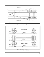
4-11.3
Mounting Tire and Wheel (Hub Type)
a.
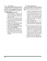
Make sure that all mounting surfaces are
clean and free of rust, dirt or paint. A wire
brush may be used to clean these surfaces
(See Figure 4-18)
.
b.
Position the inner disc wheel over the studs,
being careful not to damage the stud threads.
Make sure that the disc wheel is flat against
the mounting surface and that there is clear-
ance between the disc wheel taper and brake
drum.
c.
Position the outer disc wheel being careful
not to damage the stud threads. Be sure the
valve stems for both the inner and outer tire
are accessible.
d.
Install
the
flange
nut
(pilot
mount)
and
tighten
to
50
foot-pounds
using
the
sequence
in
Figure
Then
tighten
to
full
torque
of
450
to
5
00
foot-pounds
.
e.
Torque
will
drop
after
the
first
50
to
100
miles
of
operation.
Check
the
nuts
for
proper
torque
after
this
interval
and
retighten
them.
WARNING
USE A TORQUE WRENCH TO ASSURE
PROPER TORQUE. INSUFFICIENT
TORQUE CAN CAUSE STUD BREAK-
AGE AND DAMAGE WHEEL PILOTS.
OVERTORQUE CAN OVERSTRESS
THE STUDS AND STRIP THE
THREADS.
4-12 WINCHES (OPTION)
Inspect the winch cable before and after
every
usage. If frayed wires, nicks, kinks, worn spots,
breaks or any other sign of deterioration or dam-
age is found, immediate replacement is mandatory
before further usage. If the semitrailer is going to
be out in the weather for any length of time, it is
advisable to oil the winch cable to prevent untimely
rusting and deterioration of the cable. See
Table
for lubrication specifications.
Inspect the winch mechanism thoroughly each
week to insure safe, efficient operation.
WARNING
DO NOT HANDLE THE WINCH CABLE
WHEN THE WINCH IS IN THE ENGAGE
POSITION. HANDS OR CLOTHING
COULD GET CAUGHT IN THE CABLE
AND BE PULLED INTO THE SPOOL
CAUSING SERIOUS PERSONAL IN-
JURY.
4-13 HYDRAULIC ENGINE PACKAGE (OPTION)
The hydraulic engine package should be in-
spected weekly to insure continued proper opera-
tion. The inspection should include:
4-13.1
Check the hydraulic oil level weekly, or
after any leakage. See
Table 4-1
for proper
hydraulic oil. With all hydraulic cylinders in
the retracted position and with the engine
stopped, check the hydraulic oil level.
4-13.2
Check hoses weekly for cracks or leaks.
If a valve or line leaks, it should be replaced
immediately.
4-13.3
Check the engine oil each time before
using. Oil level should be maintained be-
tween the “ADD” and “FULL” marks on the
oil dip stick. For further maintenance proce-
dures and proper lubrication specifications,
please refer to the engine owner’s manual
that was supplied with the hydraulic engine
package.
4-13.4
Replace hydraulic filter with new filter at
least every 6 months or more often under
adverse conditions.
4-13.5
Use the fuel recommended for the en-
gine package installed on you trailer.
4-26
Summary of Contents for 825A
Page 8: ......
Page 12: ......
Page 14: ...3 2 Figure 3 1 Model 825 Trailer Terminology Figure 3 2 Service Hookups...
Page 18: ...3 6 Figure 3 3 Hydraulic Controls...
Page 22: ...3 10 Figure 3 5 Swingout Outrigger Platform Extension...
Page 24: ...3 12 Figure 3 6 Gooseneck Attachment to Frame...
Page 34: ......
Page 36: ...4 2 Figure 4 1 Lubrication Points...
Page 40: ...4 6 Figure 4 2 Model 825A Wiring Diagram...
Page 43: ...4 9 Figure 4 4 Tandem Axle Air Ride Suspension System...
Page 44: ...4 10 Figure 4 5 Tandem Axle W Flip Air Ride Suspension System...
Page 47: ...4 13 Figure 4 8 Checking Axle Alignment Figure 4 9 Examples of Camber...
Page 52: ...4 18 Figure 4 12 Axle and Brake Assembly...
Page 59: ...4 25 Figure 4 18 Mounting Tires and Wheels Figure 4 19 Stud Tightening Sequence...
Page 69: ...NOTES 5 9...
Page 70: ......


