3-21 ANTI-LOCK BRAKE SYSTEM (ABS)
Vehicle standards FMVSS No. 121, anti-lock
brake system requires all trailers manufactured af-
ter March 1, 1998 with air brake systems to have
ABS. Each trailer (including a trailer converter
dolly) shall be equipped with an anti-lock brake
system that controls the wheels of at least one
axle of the trailer. Wheels on other axles of the
trailer may be indirectly controlled by the anti-lock
brake system.
NHTSA Docket 92-29; notice 11 published
September 23, 1996 specifies the ABS warning
light be mounted near the rear of the left side of
the trailer
(See Figure 3-1)
.
·
Decal or lens marking with ABS to identify
the lamp.
·
The lamp must illuminate one time whenever
power is supplied to the ABS. At any time
the light remains on when power is supplied
there is a malfunction to the system.
The ABS used on the semitrailer is a commer-
cial unit. Single axle trailers use a two sensor, one
modulator system. Tandem axle semitrailers use a
four sensor, two modulator system. Sensors are lo-
cated at each hub of the front and rear axles, and
each modulator controls one side of the trailer.
The ABS is constant powered by the auxiliary
(blue) circuit, center pin on the semitrailer seven
way electrical connector. This circuit must be hot
whenever the tractor keyswitch is on. This circuit
must also not be used to power any additional
electrical devices while the semitrailer is moving
forward. However, additional devices such as re-
mote controls may be powered from the auxiliary
circuit while the semitrailer is stationary. Back up
power to the ABS is supplied through the stop
lamp (red) circuit, No. 4 pin on the seven way con-
nector, and ground is supplied by the white wire,
No. 1 pin.
CAUTION
THE AUXILIARY (BLUE) CIRCUIT IS
FOR POWERING THE SEMITRAILER
ABS. THIS CIRCUIT MUST BE HOT
WHEN THE TRACTOR KEY SWITCH IS
ON. NO OTHER ELECTRICAL DEVICES
MAY BE POWERED BY THIS CIRCUIT
WHILE THE SEMITRAILER IS MOVING
FORWARD.
Malfunction in the ABS is signaled by illumina-
tion of the ABS warning lamp located at the left
rear side of the semitrailer. The warning lamp will
come on and stay on while power is supplied to
the ABS on a moving vehicle, if there is a fault. If a
fault in the ABS exists, normal braking will still oc-
cur, but wheels may lock. The semitrailer is still op-
erable, but the system should be serviced as soon
as possible.
CAUTION
IF A FAULT EXISTS IN THE SEMI-
TRAILER ABS, NORMAL BRAKING
WILL OCCUR, BUT WHEELS MAY
LOCK. SERVICE THE ABS AS SOON
AS POSSIBLE.
The ABS is also equipped with a Blink Code
Diagnostic Tool mounted at the right rear corner of
the trailer
(See Figure 3-1)
. This tool is used to
identify faults that may occur in the ABS so that
they may be repaired.
Refer to ABS maintenance manual supplied
with semitrailer to answer basic questions for the
anti-lock brake system, obtain outline procedures
on how to adjust, test, remove, and install ABS
components, as well as how to test for faults in the
system by using “Blink Code Diagnostics”; and il-
lustrates ABS components, wiring, and plumbing
installation diagrams.
3-20
Summary of Contents for 825A
Page 8: ......
Page 12: ......
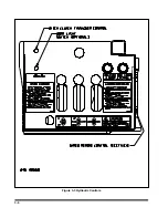
Page 14: ...3 2 Figure 3 1 Model 825 Trailer Terminology Figure 3 2 Service Hookups...
Page 18: ...3 6 Figure 3 3 Hydraulic Controls...
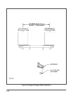
Page 22: ...3 10 Figure 3 5 Swingout Outrigger Platform Extension...
Page 24: ...3 12 Figure 3 6 Gooseneck Attachment to Frame...
Page 34: ......
Page 36: ...4 2 Figure 4 1 Lubrication Points...
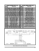
Page 40: ...4 6 Figure 4 2 Model 825A Wiring Diagram...
Page 43: ...4 9 Figure 4 4 Tandem Axle Air Ride Suspension System...
Page 44: ...4 10 Figure 4 5 Tandem Axle W Flip Air Ride Suspension System...
Page 47: ...4 13 Figure 4 8 Checking Axle Alignment Figure 4 9 Examples of Camber...
Page 52: ...4 18 Figure 4 12 Axle and Brake Assembly...
Page 59: ...4 25 Figure 4 18 Mounting Tires and Wheels Figure 4 19 Stud Tightening Sequence...
Page 69: ...NOTES 5 9...
Page 70: ......

