


3-5 TRACTOR AND SEMITRAILER CHECK-OUT
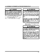
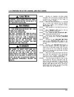
WARNING
FAILURE TO PROPERLY SET AND
CHECK PARKING BRAKE, AND
CHOCK WHEELS WHEN PARKING
AND DURING STORAGE, COULD AL-
LOW
MOVEMENT
OF
THE
TRUCK/SEMITRAILER RIG RESULT-
ING IN SERIOUS PERSONAL INJURY,
DEATH, OR DAMAGE TO PROPERTY
IN ITS PATH.
CAUTION
FAILURE TO SUPPORT THE SEMI-
TRAILER FULLY ON THE LOAD
BLOCKS DURING TRANSPORT, MAY
RESULT IN DAMAGE TO THE LOAD,
THE SEMITRAILER, AND POSSIBLE
SERIOUS INJURY OR DEATH TO INDI-
VIDUALS NEAR THE SEMITRAILER.
3-5.1
Activate the hydraulic power source.
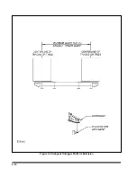
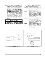
3-5.2
Using the
TRAILER LIFT
lever, lift the
trailer up until the load blocks can be low-
ered into position
(See Figure 3-1)
.
3-5.3
Activate the
TRAILER LIFT lever (See
Section 3-9)
“DOWN” until the semitrailer
rests completely on the load blocks
(See
Figure 3-1)
.
3-5.4
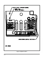
Check the operation of all lights and sig-
nals on the semitrailer for proper response to
switch positions (stop, right turn, left turn,
and clearance). Check operation of remote
function if present.
3-5.5
Check tire inflation, adjust as needed to
the pressure listed on the semitrailer VIN
plate, located on the front of the semitrailer.
3-5.6
Check tractor/semitrailer for air leaks. If
air leakage is found, repair the defect before
transporting.
3-5.7
Check the oil in each hub for proper
level and freedom from contamination. If
hubs are contaminated with water, dirt or
some other foreign material, clean before
transporting.
3-5.8
Check tractor air pressure. Pressure
must not fall below 90 psi, even after activat-
ing brakes a couple of times. Set parking
brake and carefully remove all wheel chocks.
Set emergency brake and try pulling forward.
The semitrailer wheels must not rotate. If
semitrailer brakes do not apply,
DO NOT
transport until defect, or defects, are re-
paired.
3-5
Summary of Contents for 825A
Page 8: ......
Page 12: ......
Page 14: ...3 2 Figure 3 1 Model 825 Trailer Terminology Figure 3 2 Service Hookups...
Page 18: ...3 6 Figure 3 3 Hydraulic Controls...
Page 22: ...3 10 Figure 3 5 Swingout Outrigger Platform Extension...
Page 24: ...3 12 Figure 3 6 Gooseneck Attachment to Frame...
Page 34: ......
Page 36: ...4 2 Figure 4 1 Lubrication Points...
Page 40: ...4 6 Figure 4 2 Model 825A Wiring Diagram...
Page 43: ...4 9 Figure 4 4 Tandem Axle Air Ride Suspension System...
Page 44: ...4 10 Figure 4 5 Tandem Axle W Flip Air Ride Suspension System...
Page 47: ...4 13 Figure 4 8 Checking Axle Alignment Figure 4 9 Examples of Camber...
Page 52: ...4 18 Figure 4 12 Axle and Brake Assembly...
Page 59: ...4 25 Figure 4 18 Mounting Tires and Wheels Figure 4 19 Stud Tightening Sequence...
Page 69: ...NOTES 5 9...
Page 70: ......