


4-12 WINCHES
Inspect the winch cable before and after
every
usage. If frayed wires, nicks, kinks, worn spots,
breaks or any other sign of deterioration or dam-
age is found, immediate replacement is mandatory
before further usage. If the semitrailer is going to
be out in the weather for any length of time, it is
advisable to oil the winch cable to prevent untimely
rusting and deterioration of the cable. See
Table
for lubrication specifications.
Inspect the winch mechanism thoroughly each
week to insure safe, efficient operation.
WARNING
DO NOT HANDLE THE WINCH CABLE
WHEN THE WINCH IS IN THE ENGAGE
POSITION. HANDS OR CLOTHING
COULD GET CAUGHT IN THE CABLE
AND BE PULLED INTO THE SPOOL
CAUSING SERIOUS PERSONAL IN-
JURY.
4-13 DOCK LEVELERS
4-13.1
Perform the following service procedure
on a yearly basis:
a.
Change oil with legs fully extended.
b.
After oil change, operate the dock leveler at
least three full cycles (complete leg strokes)
to bleed air from system.
c.
Fully extend legs. Clean extended legs.
Coat lightly with clean grease and grease ale-
mite fitting on each leg and check valve.
d.
Check all hydraulic lines and fittings for
leaks and worn spots. Replace any defective
lines and fittings.
e.
Check for loose bolts and nuts.
4-13.2
Disassembly/Assembly Procedure
When disassembling and reassembling the leg,
care should be taken to keep all parts clean and to
prevent parts from being damaged. All seals
should be coated lightly with grease before reas-
sembling the leg.
4-13.3
Lock Valve (See Figure 4-21)
a.
Remove retaining plug.
b.
Remove o-ring plug opposite retaining plug
on rectangular block.
c.
Using a drift small enough to fit through the
port opened in the previous step, tap out the
lock valve cartridges.
d.
Install new lock valve cartridges back to
back (as illustrated). Grease o-rings.
e.
Install two new o-rings and two back-up
washers on retaining plug.
f.
Thread retaining plug into body (tap gently
to engage threads). Torque plug to 15 ft.lbs.
g.
Install new o-ring on plug, opposite retaining
plug. Thread plug into body. Torque to 70
in.lbs.
h.
Replace spring and poppet. Replace the o-
ring on plug and reinstall.
i.
Install new o-rings and back-up washers on
top of piston rod.
j.
Thread lock valve on piston rod until firmly
seated. If the ports need to be relocated,
loosen the screw at the top of the well tube
and turn lock valve clockwise until ports are at
the desired location. Retighten the set screw.
4-30
Summary of Contents for 600B Series
Page 8: ......
Page 12: ......
Page 14: ...3 2 Figure 3 1 Front Trailer Terminology Figure 3 2 Rear Trailer Terminology...
Page 18: ...3 6 Figure 3 4 Hydraulic Controls...
Page 26: ...3 14 Figure 3 7 Steps for Loading and Unloading...
Page 32: ...3 20 Figure 3 10 Dock Leveler Operation...
Page 38: ...3 26 Figure 3 14 Rear Impact Guard and Antilock Brake System...
Page 42: ...4 2 Figure 4 1 Lubrication Points...
Page 48: ...4 8 Figure 4 3 600B Wiring Diagram...
Page 49: ...4 9 Figure 4 4 Remote Wiring Diagram...
Page 52: ...4 12 Figure 4 5 Tandem Axle Air Ride Suspension System Figure 4 6 Air Ride Height Adjustment...
Page 54: ...4 14 Figure 4 7 Triple Axle Air Ride Suspension System...
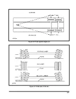
Page 57: ...4 17 Figure 4 9 Checking Axle Alignment Figure 4 10 Examples of Camber...
Page 61: ...4 21 Figure 4 13 Axle and Brake Assembly...
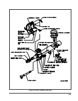
Page 71: ...4 31 Figure 4 21 Dock Leveler Leg Assembly...
Page 73: ...4 33 Figure 4 22 Crank Landing Gear Assembly...
Page 84: ...NOTES 5 10...


