


3-15 WORK LIGHT (OPTIONAL)
The WORK LIGHT SWITCH is on the hydraulic
control panel. It illuminates the hydraulic control
panel and controls the optional work lights
mounted on the bulkhead. The work lights illumi-
nate the upper deck.
3-16 WINCH CONTROLS
DANGER
1. THE WINCH IS NOT DESIGNED OR
INTENDED TO BE USED FOR LIFTING
OR MOVING PEOPLE. USING IT THIS
WAY CAN CAUSE SERIOUS INJURY
OR DEATH.
2. MAKE CERTAIN THE WINCH CABLE
SPOOL CLUTCH IS SET TO ENGAGE
AND CLUTCH IS FULLY ENGAGED BE-
FORE LOAD TENSION IS APPLIED TO
WINCH CABLE. NEVER ATTEMPT TO
DISENGAGE THE WINCH CABLE
SPOOL WHEN THE CABLE IS UNDER
TENSION. LOSS OF LOAD CONTROL,
PROPERTY DAMAGE, INJURY OR
DEATH CAN RESULT.
3. FAILURE TO LEAVE AT LEAST FIVE
WINCH CABLE WRAPS ON THE WINCH
CABLE SPOOL COULD ALLOW THE
CABLE TO COME OFF THE SPOOL,
RESULTING IN SERIOUS PERSONAL
INJURY OR DEATH.
WARNING
DO NOT HANDLE THE WINCH CABLE
WHEN THE WINCH IS IN THE ENGAGE
POSITION. HANDS OR CLOTHING
COULD GET CAUGHT IN THE CABLE
AND BE PULLED INTO THE SPOOL
CAUSING SERIOUS PERSONAL IN-
JURY.
3-16.1
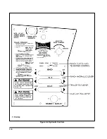
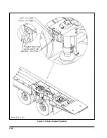
The
WINCH HYDRAULIC
lever
(See
is the top lever located
on the control panel. It is a three position
control:
IN
This position will cause the winch to
reel cable onto the winch spool when
the winch clutch handle is engaged.
CENTER
This is the neutral position. This po-
sition will not operate the winch.
OUT
This position will cause the winch to
reel cable off of the winch spool
when the winch is engaged.
3-17
Summary of Contents for 600B Series
Page 8: ......
Page 12: ......
Page 14: ...3 2 Figure 3 1 Front Trailer Terminology Figure 3 2 Rear Trailer Terminology...
Page 18: ...3 6 Figure 3 4 Hydraulic Controls...
Page 26: ...3 14 Figure 3 7 Steps for Loading and Unloading...
Page 32: ...3 20 Figure 3 10 Dock Leveler Operation...
Page 38: ...3 26 Figure 3 14 Rear Impact Guard and Antilock Brake System...
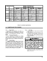
Page 42: ...4 2 Figure 4 1 Lubrication Points...
Page 48: ...4 8 Figure 4 3 600B Wiring Diagram...
Page 49: ...4 9 Figure 4 4 Remote Wiring Diagram...
Page 52: ...4 12 Figure 4 5 Tandem Axle Air Ride Suspension System Figure 4 6 Air Ride Height Adjustment...
Page 54: ...4 14 Figure 4 7 Triple Axle Air Ride Suspension System...
Page 57: ...4 17 Figure 4 9 Checking Axle Alignment Figure 4 10 Examples of Camber...
Page 61: ...4 21 Figure 4 13 Axle and Brake Assembly...
Page 71: ...4 31 Figure 4 21 Dock Leveler Leg Assembly...
Page 73: ...4 33 Figure 4 22 Crank Landing Gear Assembly...
Page 84: ...NOTES 5 10...


