


3-13.12
After bed tilt angle is fully lowered,
move the undercarriage to the rear until it is
in transport position. The trailer deck will
lower as the undercarriage rollers go into
pockets. Hold
TRAILER TILT
lever in the
down position until hydraulic system works
against the bottomed out Hydraulic Tilt Cylin-
ders (Approximately 2-5 seconds). Hold
AXLE CONTROL
lever in the transport posi-
tion until hydraulic system works against the
fully extended Hydraulic Axle Cylinder (Ap-
proximately 15-30 seconds).
3-13.13
Recheck that load is properly secured.
If necessary, unsecure the load, move load
slightly forward or rearward on the load bed
to get correct weight distribution on kingpin
and the trailer axles, and resecure the load
with the tiedowns and winch cable.
3-13.14
Shut down hydraulic power system. If
hydraulic engine package is installed, shut
down the auxiliary hydraulic power engine
following operating instructions in
Section
Assure maintenance schedule is up-
to-date and semitrailer is ready to be pulled.
3-14 UNLOADING PROCEDURE
3-14.1
Practice all standard industrial safety
standards.
3-14.2
Park the tractor/semitrailer in a straight
line on a level even surface
(See Figure
Set the tractor brakes and release the
semitrailer brakes.
3-14.3
Start operation of hydraulic power sys-
tem. If the hydraulic engine package is in-
stalled, start and warm up the auxiliary hy-
draulic power engine following engine operat-
ing instructions in
Section 3-18.
3-14.4
Move load as far forward as is practical
on the trailer and secure with appropriate
load tiedowns.
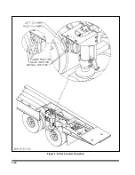
3-14.5
Using the
AXLE CONTROL
lever
(See
Section 3-10)
, move undercarriage forward
(out of pockets) five to eight feet, or just be-
hind the center of gravity of the loaded semi-
trailer. This is to insure that the trailer does
not rock back. Actual center of gravity will re-
locate to the rear as the trailer is tilted up.
CAUTION
DO NOT ALLOW THE BACK SEMI-
TRAILER AXLE TO LEAVE THE
GROUND. THIS CAN RESULT IN DAM-
AGE TO THE SEMITRAILER.
3-14.6
Using the
TRAILER TILT
lever
(See
Section 3-9),
raise the front of bed up to full
tilt position reeling out winch cable as
needed to keep slight tension on the cable.
3-14.7
If the approach plate has not touched
the ground, move the undercarriage forward
until the approach plate touches the ground
and starts supporting the trailer. Then alter-
nate between moving the undercarriage for-
ward while lowering the tilt angle and reeling
in the winch cable. The object is to keep a
part of the weight on the approach plate, and
part of the weight on the wheels while lower-
ing the tilt angle and keeping slight tension
on the winch cable. Always use low load an-
gle to unload powered products. To achieve
low load angle, the undercarriage has to be
all the way forward. The maximum load an-
gle is only intended, if required, for unloading
non-powered products and to transfer load to
tractor. Transfer load to tractor by raising
deck and moving axles toward rear until load
is forward of rear axle, thus transferring load
to tractor.
WARNING
ALWAYS USE LOW LOAD ANGLE TO
LOAD AND UNLOAD POWERED
PRODUCTS.
3-15
Summary of Contents for 600B Series
Page 8: ......
Page 12: ......
Page 14: ...3 2 Figure 3 1 Front Trailer Terminology Figure 3 2 Rear Trailer Terminology...
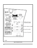
Page 18: ...3 6 Figure 3 4 Hydraulic Controls...
Page 26: ...3 14 Figure 3 7 Steps for Loading and Unloading...
Page 32: ...3 20 Figure 3 10 Dock Leveler Operation...
Page 38: ...3 26 Figure 3 14 Rear Impact Guard and Antilock Brake System...
Page 42: ...4 2 Figure 4 1 Lubrication Points...
Page 48: ...4 8 Figure 4 3 600B Wiring Diagram...
Page 49: ...4 9 Figure 4 4 Remote Wiring Diagram...
Page 52: ...4 12 Figure 4 5 Tandem Axle Air Ride Suspension System Figure 4 6 Air Ride Height Adjustment...
Page 54: ...4 14 Figure 4 7 Triple Axle Air Ride Suspension System...
Page 57: ...4 17 Figure 4 9 Checking Axle Alignment Figure 4 10 Examples of Camber...
Page 61: ...4 21 Figure 4 13 Axle and Brake Assembly...
Page 71: ...4 31 Figure 4 21 Dock Leveler Leg Assembly...
Page 73: ...4 33 Figure 4 22 Crank Landing Gear Assembly...
Page 84: ...NOTES 5 10...


