MAINTENANCE AND LUBRICATION
4-11
Electrical System
1.
Maintenance of the electrical system consists of
inspection and minor servicing. Any wire, connection
or electrical component showing signs of corrosion,
wear, breakage or unraveling must be repaired or
replaced.
(See Figures 4-3 and 4-4 for electrical
wiring diagrams and Table 4-4 for wiring parts
list)
2.
Frayed or unraveling wire must have the defective
section removed and replaced with wire of the same
color and gauge. Seal all connections and insulate.
3.
Corroded terminals must have the corrosion
removed, source of corrosion neutralized and the
terminals resealed, protected, and insulated.
4.
Fuse or circuit breaker burn-out or blow-out usually
indicates an electrical short-circuit, although a fuse
can occasionally fail from vibration. Insert a second
fuse or reset the breaker. If this fuse immediately
burns out or the breaker trips, locate the cause of the
electrical short and repair.
5.
A light that repeatedly burns-out usually indicates a
loose connection, poor system ground, or a
malfunctioning voltage regulator. Locate the source
of the problem and repair. System grounds must be
grounded to bare metal surfaces. Paint, grease, wax,
and other coatings act as insulators. Replacement
lamps must be equivalent to the factory installed
lamp.
Suspension Maintenance
Air Ride Suspension
1.
for Tandem and Triple Axle
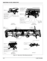
Air Ride Suspension drawings.
2.
Physically check all nuts, bolts, and air line fittings for
proper torque (see torque chart below).
* Air Spring Connections Only.
** First number listed is torque required if bolt head
designated with Neway; Second number listed is torque
required if bolt head designated with Holland Neway.
3.
Check all other suspension components for any sign
of damage, looseness, wear or cracks.
4.
With trailer on level surface and air pressure in
excess of 65 psi, all air springs should be of equal
firmness. The height control valve on right side of
front axle controls all air springs on tandem axle
suspensions.
5.
The height control valve on right side of center axle
controls ride height for all air springs on triple axle
suspension.
Tandem Axle Air Ride Height
Adjustment
1.
Before adjusting, the vehicle must be empty with the
kingpin at operating height and have air supplied to
the trailer.
2.
Disconnect linkage at the control arm and raise
control arm to the “up” position, raising the trailer until
a block can be placed between axle tube and
undercarriage frame
3.
Position the wood block between the axle tube and
frame according to table below. Block height is
dependent upon suspension ride height and/or axle
brake size.
4.
Lower the trailer by exhausting air from the air
springs by moving the control arm to the “down”
position (about 45°) until the axle tube is resting on
the block.
5.
Check the ride height to make sure it is correct.
Consult Landoll Service Center if correct height
cannot be obtained.
AIR SUSPENSION TORQUE CHART
Size
1-1/8”-7
1/2”-13
*3/4”-16
3/4”-10
Torque in
Ft. Lbs.
**800
or
550
35
35
150
AIR SUSPENSION RIDE HEIGHT AND BLOCK
Brake Size
Ride Height
Block Height
12-1/4” Dia.
3.5"
3"
16-1/2” Dia.
5.5"
5"
Summary of Contents for 425B Series
Page 2: ......
Page 6: ...iv F 543 1011 Edition...
Page 14: ...2 6 F 543 1011 Edition STANDARD SPECIFICATIONS...
Page 26: ...3 12 F 543 1011 Edition OPERATING INSTRUCTIONS Figure 3 7 Steps for Loading and Unloading...
Page 32: ...3 18 F 543 1011 Edition OPERATING INSTRUCTIONS Figure 3 12 Dock Leveler Operation...
Page 61: ...MAINTENANCE AND LUBRICATION 4 21 Figure 4 13 Axle and Brake Assembly...
Page 76: ...4 36 F 543 1011 Edition MAINTENANCE AND LUBRICATION Page Intentionally Blank...
Page 86: ...5 10 F 543 1011 Edition TROUBLESHOOTING GUIDE...
Page 87: ......


