
LANCOM
1781VAW
Quick Reference Guide
. . . c o n n e c t i n g y o u r b u s i n e s s
LANCOM, LANCOM S
ystems and L
COS ar
e r
egister
ed tr
ademarks. All other names or descriptions used may be tr
ademarks or r
egister
ed tr
ademarks of their owners. Subject to change without notice. N
o liability for
technical err
ors and/or omissions. 111074/0614
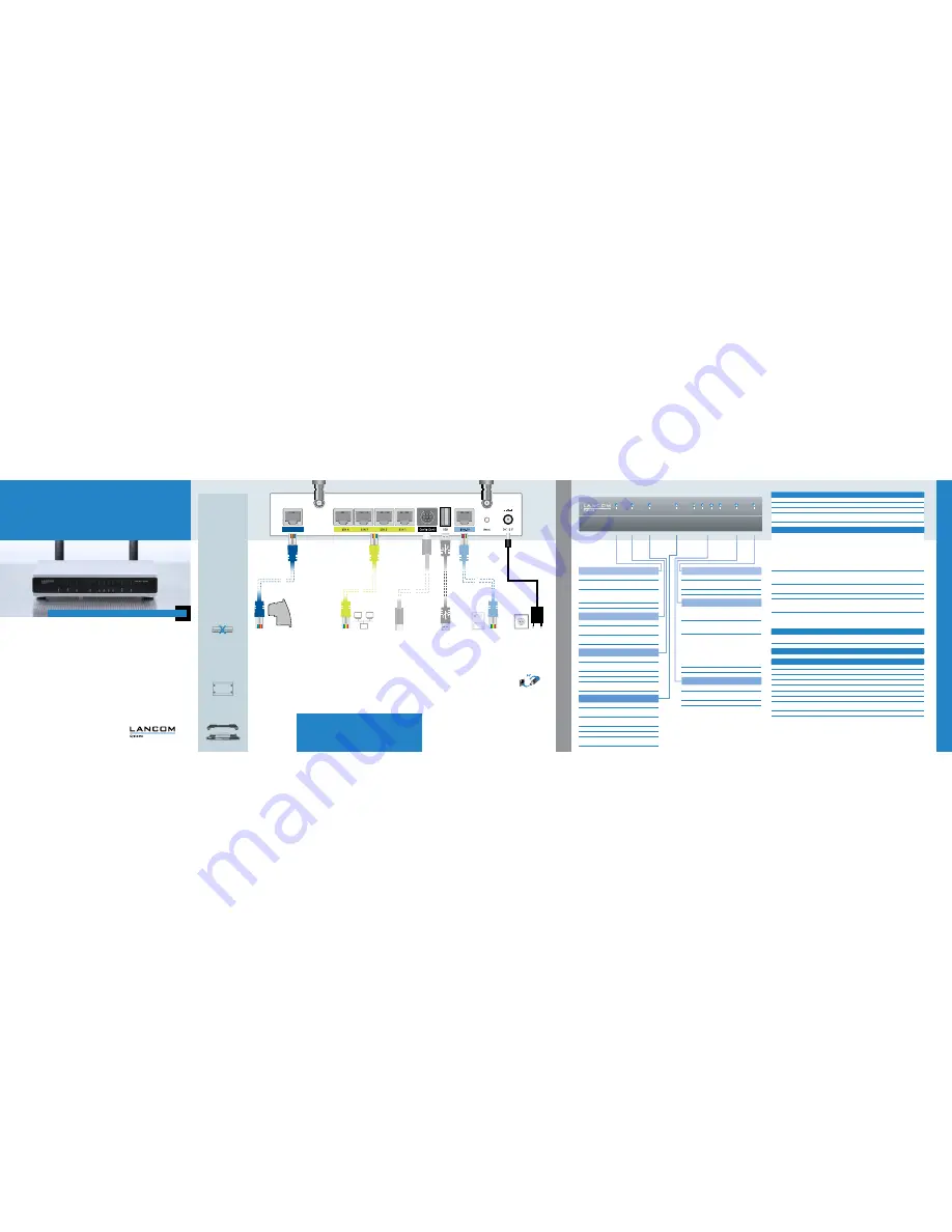
d
Optional: Serial
configuration cable
You can connect the
device to a PC with a
configuration cable
(available separately).
c
LAN cable
Use the cable with the
kiwi-colored connectors
to connect one of the
interfaces ETH1 to ETH4
to your PC or a LAN
switch.
4
Please observe the fol-
lowing when setting up
the device
1
For devices to be
operated on the
desktop, please attach
the adhesive rubber
footpads
1
Do not rest any objects
on top of the device
1
Keep the ventilation
slots on the side of
the device clear of
obstruction
1
In case of wall
mounting, use the
drilling template as
supplied
1
Rack installation with
the optional LANCOM
Rack Mount (not
supplied)
LANCOM 1681V
Power
VDSL
Online
ETH
1
ETH 2
VP
N
ETH
3
ETH 4
ISDN Statu
s
g
Power cable
When connecting the
cable to the device, turn
the bayonet connector
90° clockwise until it
clicks into place.
Use only the supplied
power adapter.
Hardware
Power supply
12 V DC, external power adapter (230 V); bayonet connector to secure against disconnection
Power consumption
Max. ca. 14 W
Environment
Temperature range 0–35 °C, humidity 0–95 %, non-condensing
Housing
Robust synthetic housing, rear connectors, ready for wall mounting, Kensington lock;
measures 210 x 45 x 140 mm (W x H x D)
Number of fans
None; fanless design, no rotating parts, high MTBF
Interfaces
LANCOM 1781VAW over ISDN
LANCOM 1781VAW over POTS
WAN: VDSL2
1
VDSL2 as per ITU G.993.2;
profiles 8a, 8b, 8c, 8d, 12a, 12b, 17a
1
Compatible to VDSL2 from Deutsche Telekom
1
Compliant to: ADSL2+ over ISDN as per
ITU G.992.5 Annex B with DPBO, ADSL2 over
ISDN as per ITU G.992.3/5 Annex B/J, ADSL
over ISDN as per ITU G.992.1 Annex B
1
Supports just one virtual connection at a time
in ATM (VPI-VCI pair)
1
VDSL2 as per ITU G.993.2;
profiles 8a, 8b, 8c, 8d, 12a, 12b, 17a
1
Compliant to: ADSL2+ over POTS as per
ITU G.992.5 Annex A/Annex M with DPBO,
ADSL2 over POTS as per ITU G.992.3 Annex A/
L, ADSL over POTS as per ITU G.992.1 Annex A
1
Supports just one virtual connection at a time
in ATM (VPI-VCI pair)
ETH
4 individual ports, 10/100/1000 Mbps Gigabit Ethernet, by default set to switch mode. Up to 3
ports can be operated as additional WAN ports. Ethernet ports can be electrically disabled in the
LCOS configuration.
USB
USB 2.0 Hi-Speed host port for connecting USB printers (USB print server), serial devices (COM-port
servers), USB data media (FAT file system), or supported UMTS USB modems
ISDN
ISDN S
0
bus
Config (Com)
Serial configuration interface / COM port (8-pin Mini-DIN):
9,600–115,000 baud, suitable for optional connection of analog/GPRS modems. Supports internal
COM-port server and provides transparent asynchronous serial-data transfer via TCP.
Ant1, Ant2
Two reverse SMA connectors for external LANCOM AirLancer Extender antennas or for antennas
from other vendors. Please respect the restrictions which apply in your country when setting up an
antenna system. For information about calculating the correct antenna setup, please refer to
www.lancom.eu.
WAN protocols
VDSL, ADSL, Ethernet PPPoE, PPPoA, IPoA, Multi-PPPoE, ML-PPP, PPTP (PAC or PNS) and IPoE (with or without DHCP),
RIP-1, RIP-2, VLAN
ISDN
1TR6, DSS1 (Euro-ISDN), PPP, X75, HDLC, ML-PPP, V.110/GSM/HSCSD
Declaration of conformity
For the declaration of conformity, see the product page on our website www.lancom-systems.eu
Package content
Manual
Hardware Quick Reference (DE/EN), Installation Guide (DE/EN/FR/ES/IT/PT/NL)
CD/DVD
Management software (LANconfig, LANmonitor, LANCAPI) and LCOS documentation
Cable
1 Ethernet cable, 3m (kiwi-colored connectors)
Cable
1 VDSL/ADSL cable, 3m (dark blue connectors)
Cable**
1 ISDN cable, 3m (light-blue connectors)
Adapter
All-IP adapter (only in the EU version)
Antennas
Two 3dBi dipole dualband antennas
Power adapter
External power supply adapter (230 V), NEST 12 V/1.5 A DC/S, barrel connector 2.1/5.5 mm bayonet,
LANCOM item no. 110723 (EU), LANCOM item no. 110829 (UK)
**)
Included only in the “over ISDN” version
A6C8DB&,-&K6L
9HA
:I='
EdlZg
:I=&
Dca^cZ
>H9C
:I=)
:I=(
KEC
LA6C
This product contains separate modem firmware with open-source software components. These are subject to their own
licenses, in particular the General Public License (GPL). The license text for the modem firmware is available on the data
medium supplied. If the respective license demands, the source files for the corresponding software components will be
made available on a download server upon request. License information for the device firmware (LCOS) is available in the file
LCOS-Licenses.txt on the data medium supplied.
a
Power
Off
Device switched off
Green on,
permanently
Device operational
Blinking
green/orange
Configuration password not set. Without a
configuration password, the configuration
data in the device is unprotected.
Blinking red
Charge or time limit reached
b
Online
Off
WAN connection inactive
Green on,
permanently
WAN connection active
Red on,
permanently
WAN connection error
g
VPN
Off
VPN connection inactive
Green on,
permanently
VPN connection active
Blinking green
Establishing VPN connections
e
ETH
Off
No networking device attached
Green on,
permanently
Connection to network device operational,
no data traffic
Flickering green
Data transmission
d
ISDN
Off
interface deactivated
Green on,
permanently
D-channel active
Orange on,
permanently
B-channel active
Flickering green
ISDN data transmission
Flickering red
ISDN transmission error
Blinking
red/orange
ISDN hardware error
e
Optional:
USB cable
Connect a USB storage
device or a USB printer to
the USB interface.
USB cable not included in
the package.
f
ISDN cable**
Use the ISDN cable with
the light-blue connec-
tors to connect the ISDN
interface to the NTBA if
you wish to use ISDN.
c
DSL
Off
interface deactivated
Green on,
permanently
DSL connection active
Flickering green
DSL data transmission
Flickering red
DSL transmission error
Blinking
red/orange
DSL hardware error
a
VDSL/ADSL cable*
Connect the cable with
the dark-blue connector
to the DSL splitter from
your provider. Please
ensure that you carefully
follow any instructions
from your provider regard-
ing the installation of the
DSL splitter and NTBA (if
applicable).
*) For operation without
splitter please use the
DSL cable supplied by
your Internet provider or
the enclosed adpter. For
further information please
contact your Internet
provider.
S
E
T
T
I
N
G
U
P
A
N
D
C
O
N
N
E
C
T
I
N
G
T
H
E
D
E
V
I
C
E
T
E
C
H
N
I
C
A
L
D
A
T
A
K9HA
6ci'
6ci&
b
WLAN antennas
Screw the two supplied
WLAN antennas onto
the connectors Ant1
and Ant2. Depending
on how the antennas
are to be used, 'Antenna
Grouping' may need to
be configured in order to
provide the desired MIMO
behavior.
f
WLAN
Off
No WLAN network defined or WLAN
module deactivated. The WLAN module is
not transmitting beacons.
Green on,
permanently
At least one WLAN network is defined
and WLAN module activated. The WLAN
module is transmitting beacons.
Green inverse
flashing
Number of flashes = number of connected
WLAN stations and P2P wireless connec-
tions, followed by a pause (default).
Alternatively the frequency of the flashing
can indicate signal strength over the
defined P2P link or the signal strength
between the access point and the device
operating in client mode.
Blinking green
DFS scanning or other scan procedure
5
When working with separately purchased antennas, please ensure you
do not exceed the maximum permissible transmission power. The system
operator is responsible for adhering to the threshold values.
Antennas are only to be attached or changed when the device is switched off.
Mounting or demounting antennas with the device switched on may cause the
destruction of the WLAN module!
5
a
c
d
b
g
e
f
a
c
d
e
f
g
b
b


